Unimog U4000/5000


Time for another Thirdwigg Unimog!

Instructions are available at Rebrickable.com.

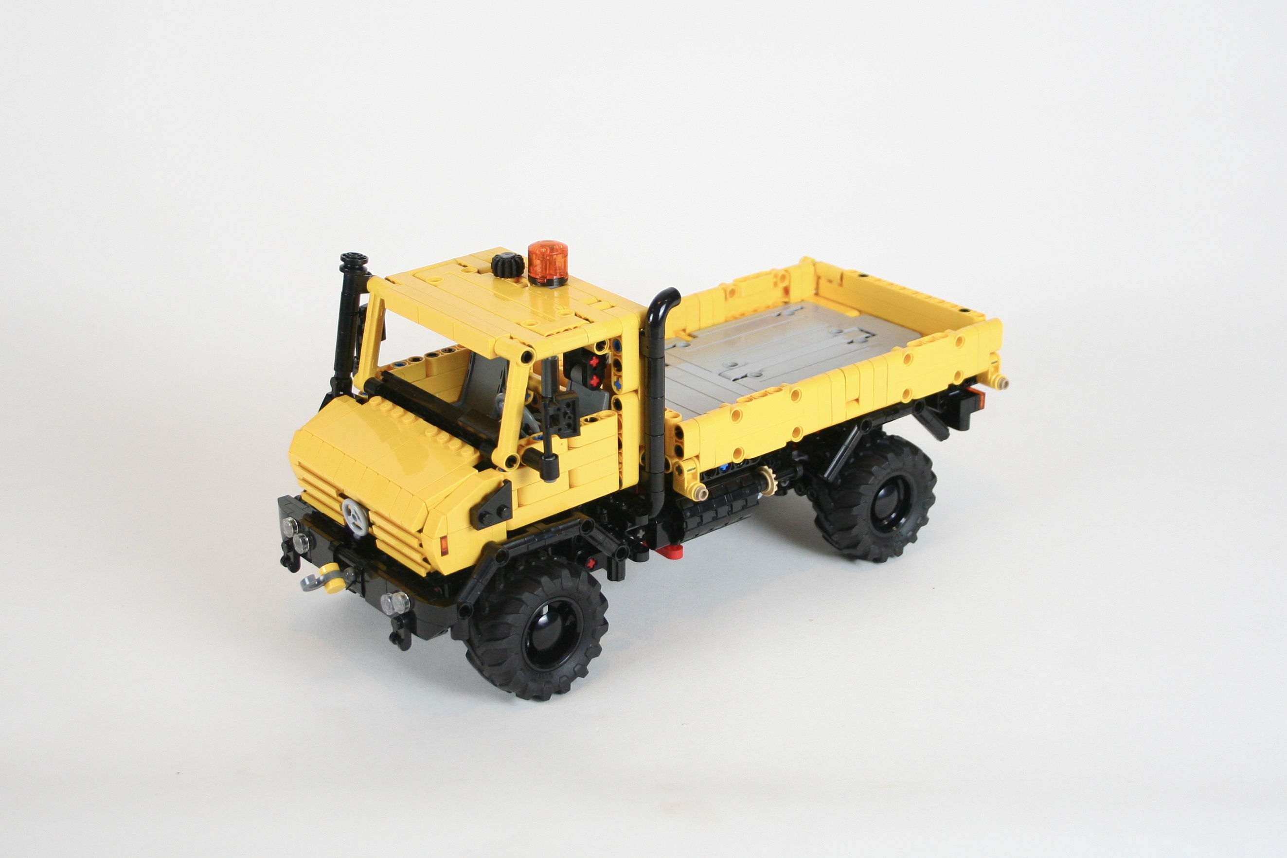
I am now averaging about one Unimog a year now, so it was about time for me to make another one. The 1:21 scale truck is now fairly common, for good reason: it’s a playful size, it does not take too much space or too many parts, and yet gives plenty of space for functions. The popularity of the U423 led me to try a U4000/5000 version.

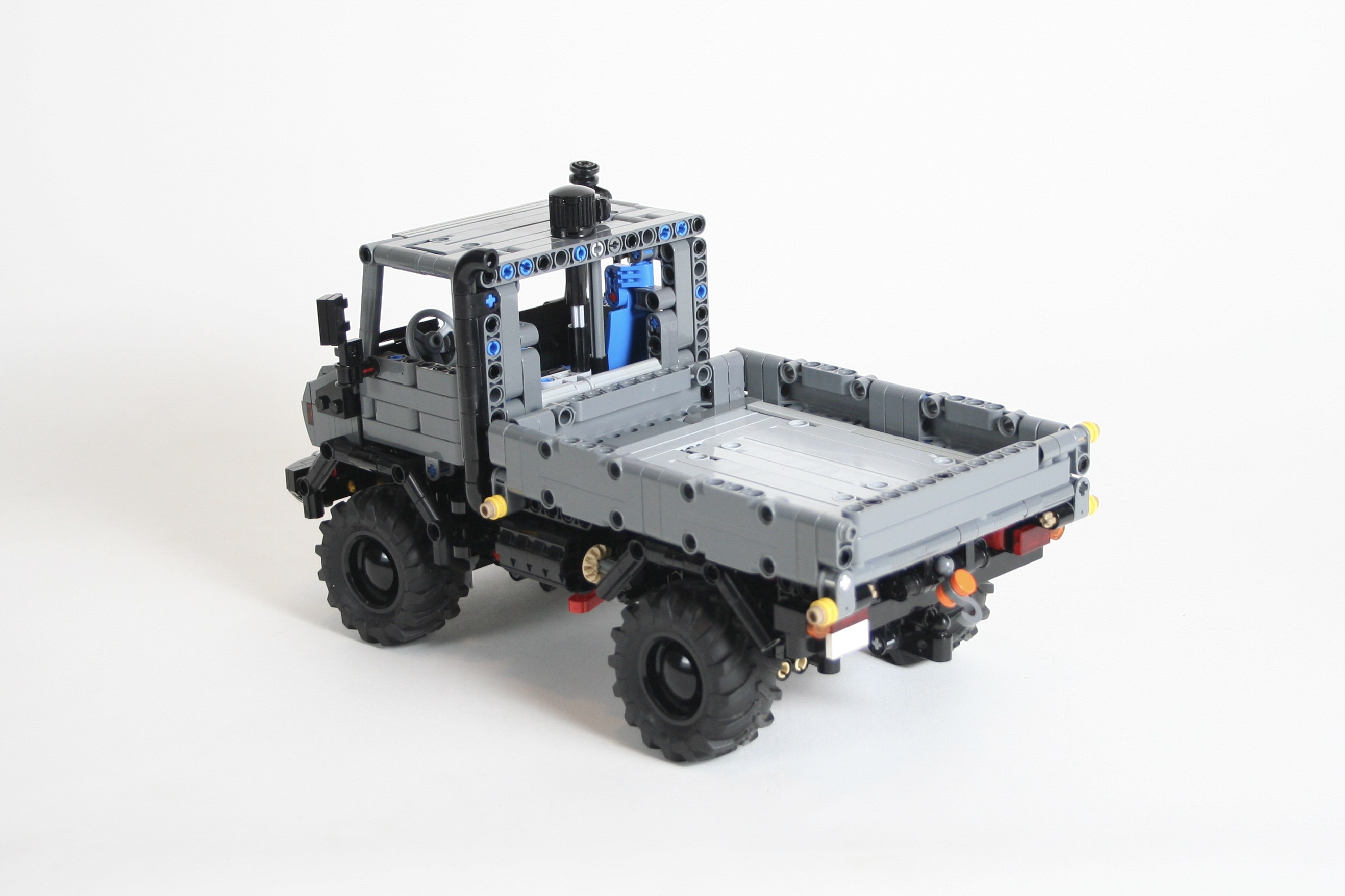
As I started designing, I wanted to have the standard functions: steering, a drivetrain, an engine. But once I placed these functions, I was left with a lot of space, and the truck was missing something to set it apart from all the other Unimogs. I added a simple two speed transmission, but I still wanted another function. After some looking at a number of photos of the U5000, I started noticing a common feature: a winch.

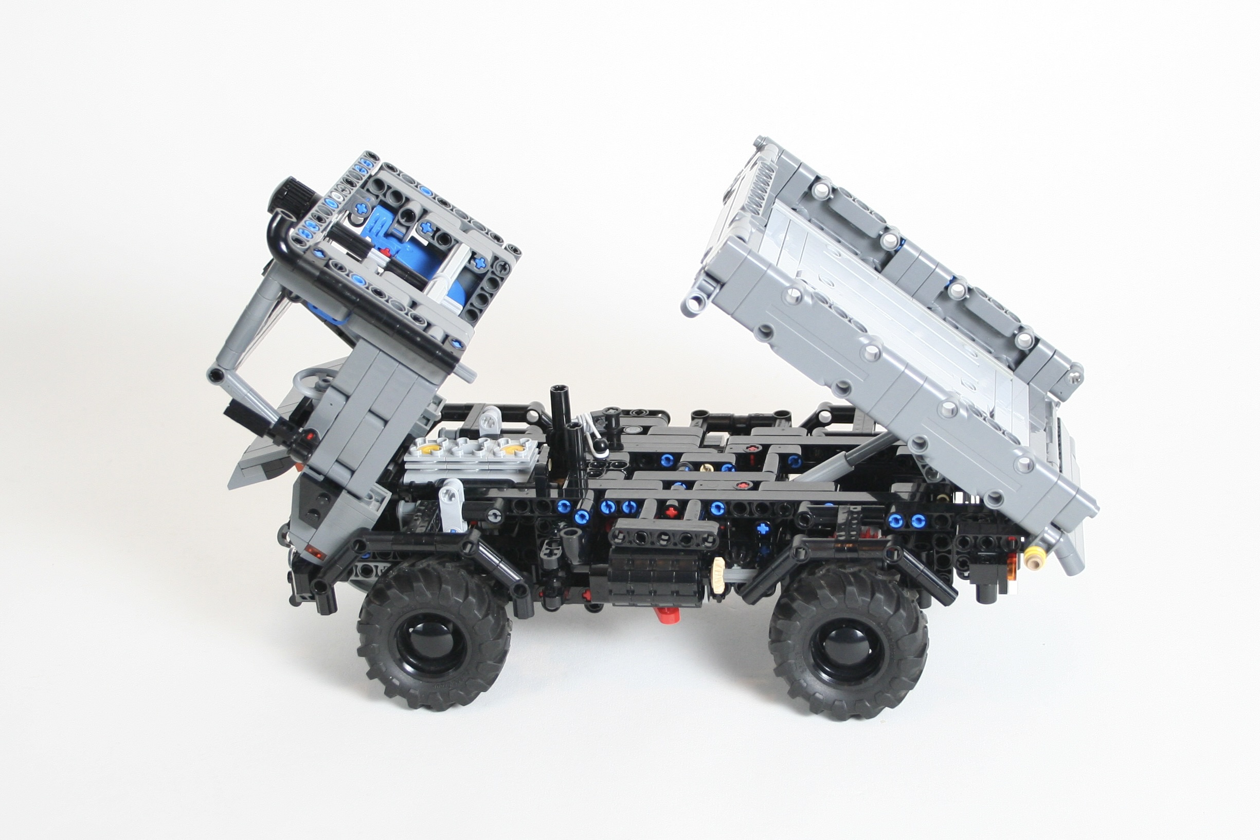
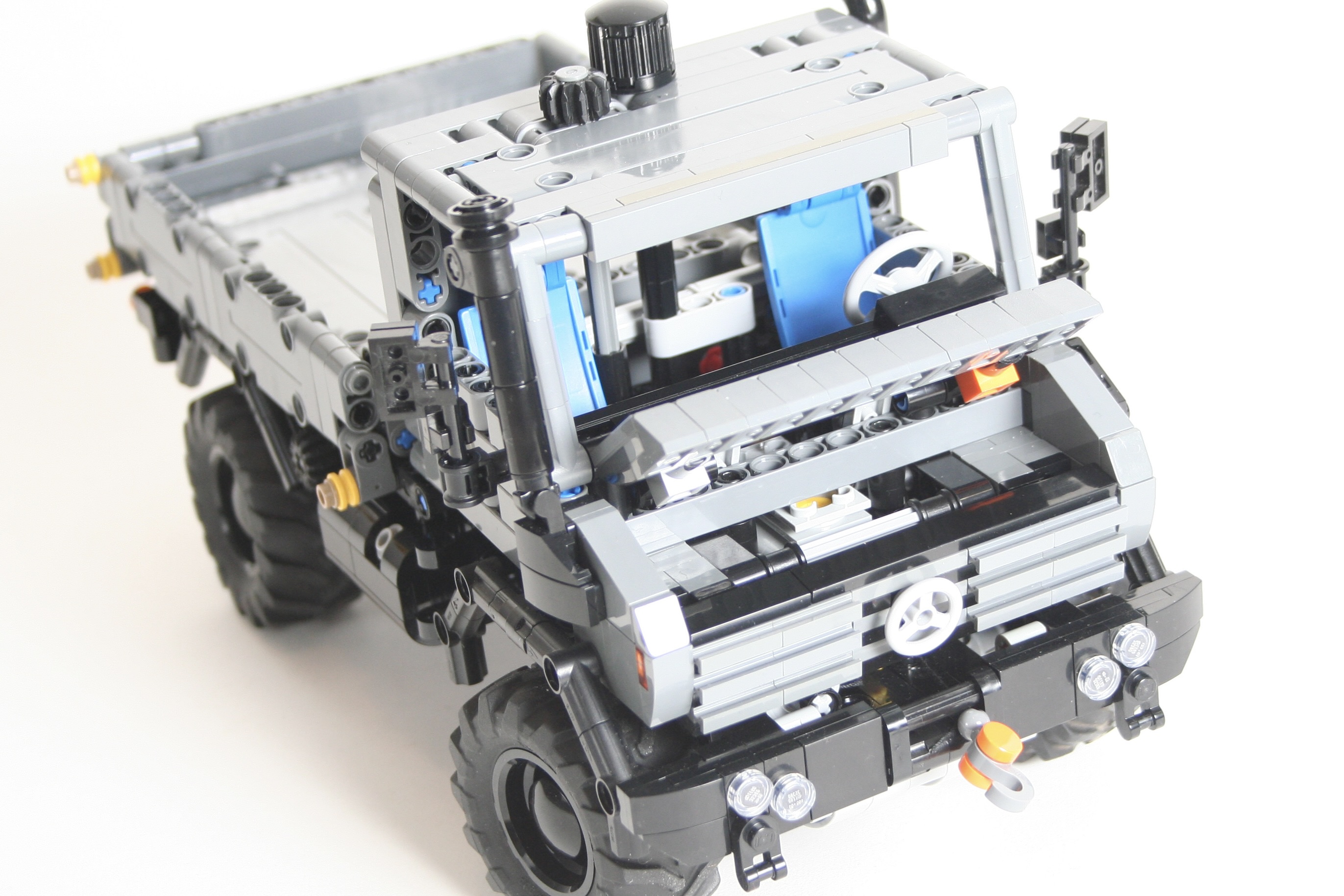
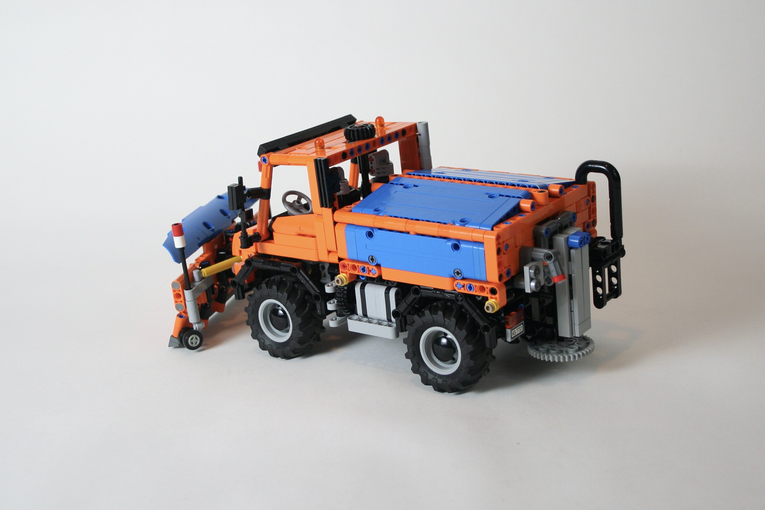
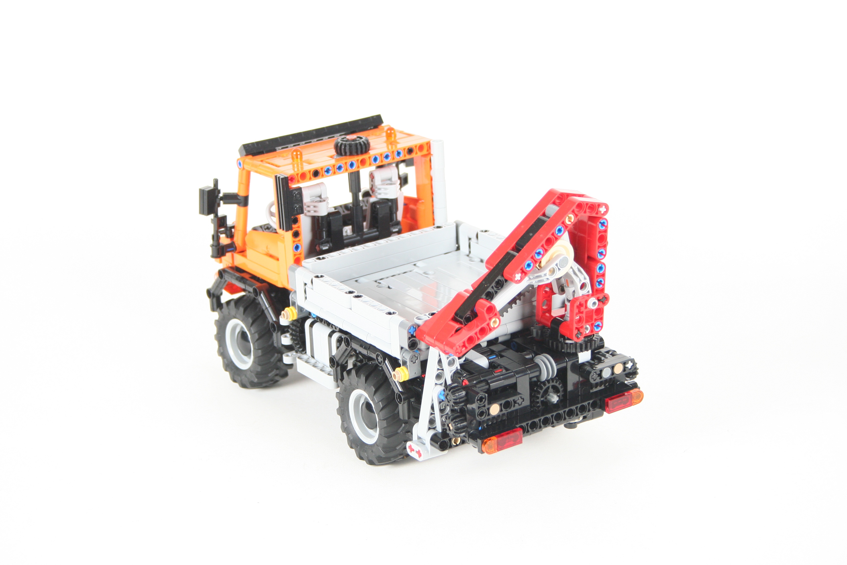
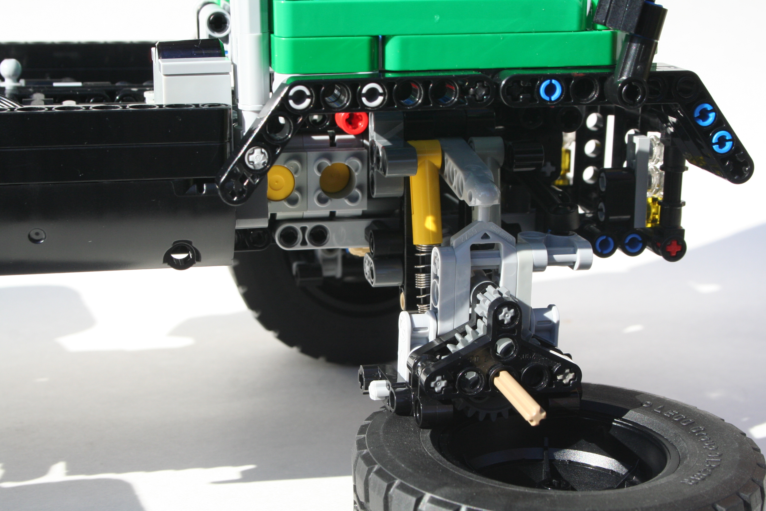
With a little bit of work, I was able to add both a front and rear winch. The front is mounted to the right of the engine with a HOG on top of the cabin next to the steering HOG. The front winch has a lock, which can be released by moving the step on the right of the truck. The rear winch is controlled by a HOG on the right of the truck, with a lock under the fuel tank.

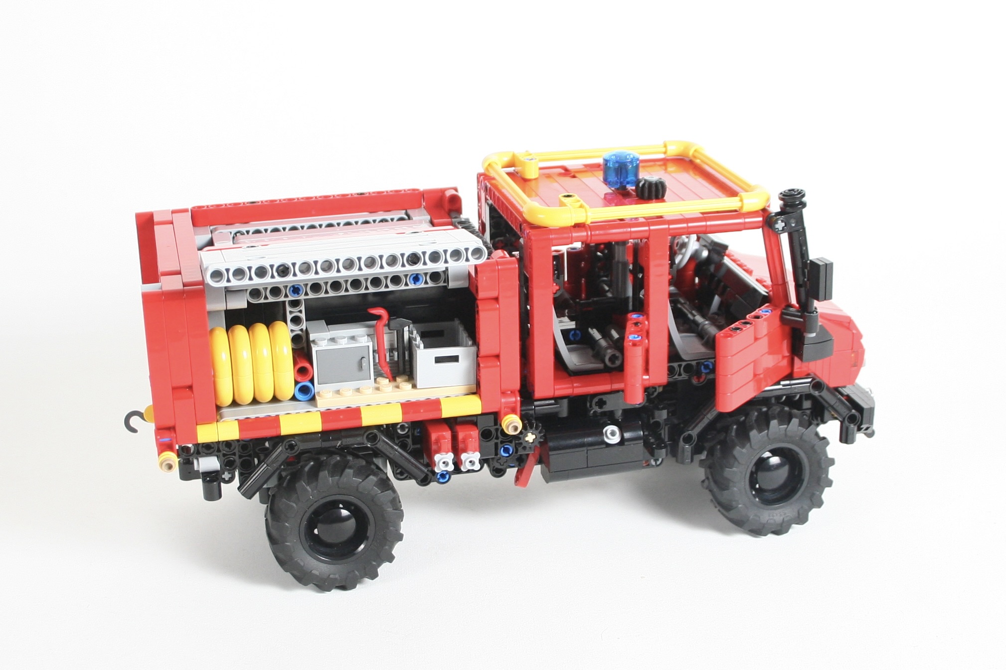
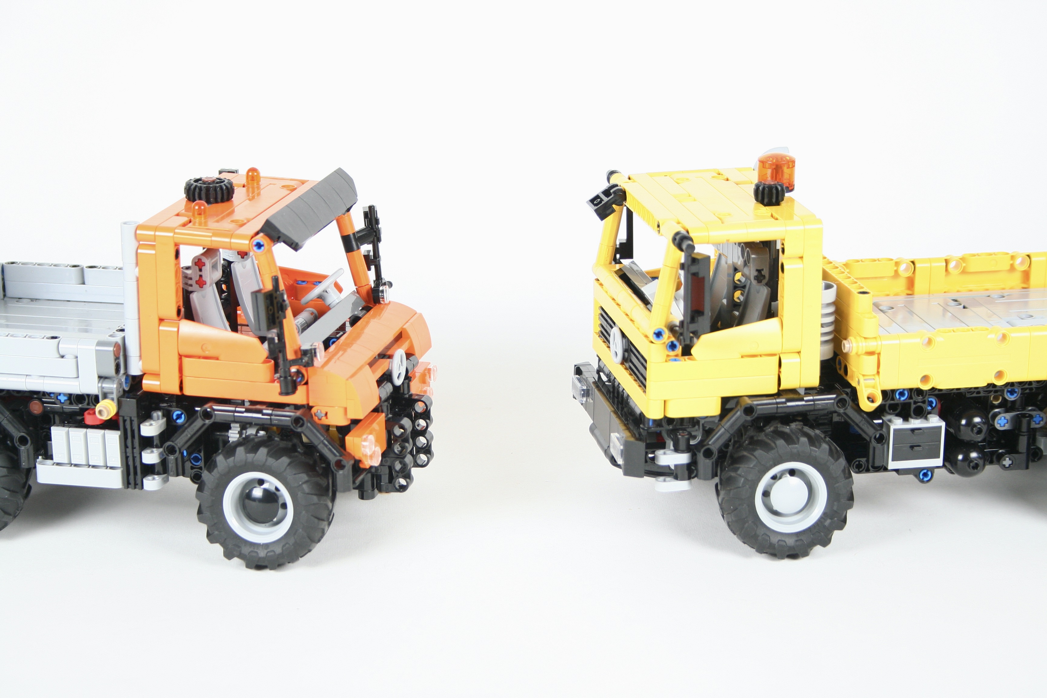
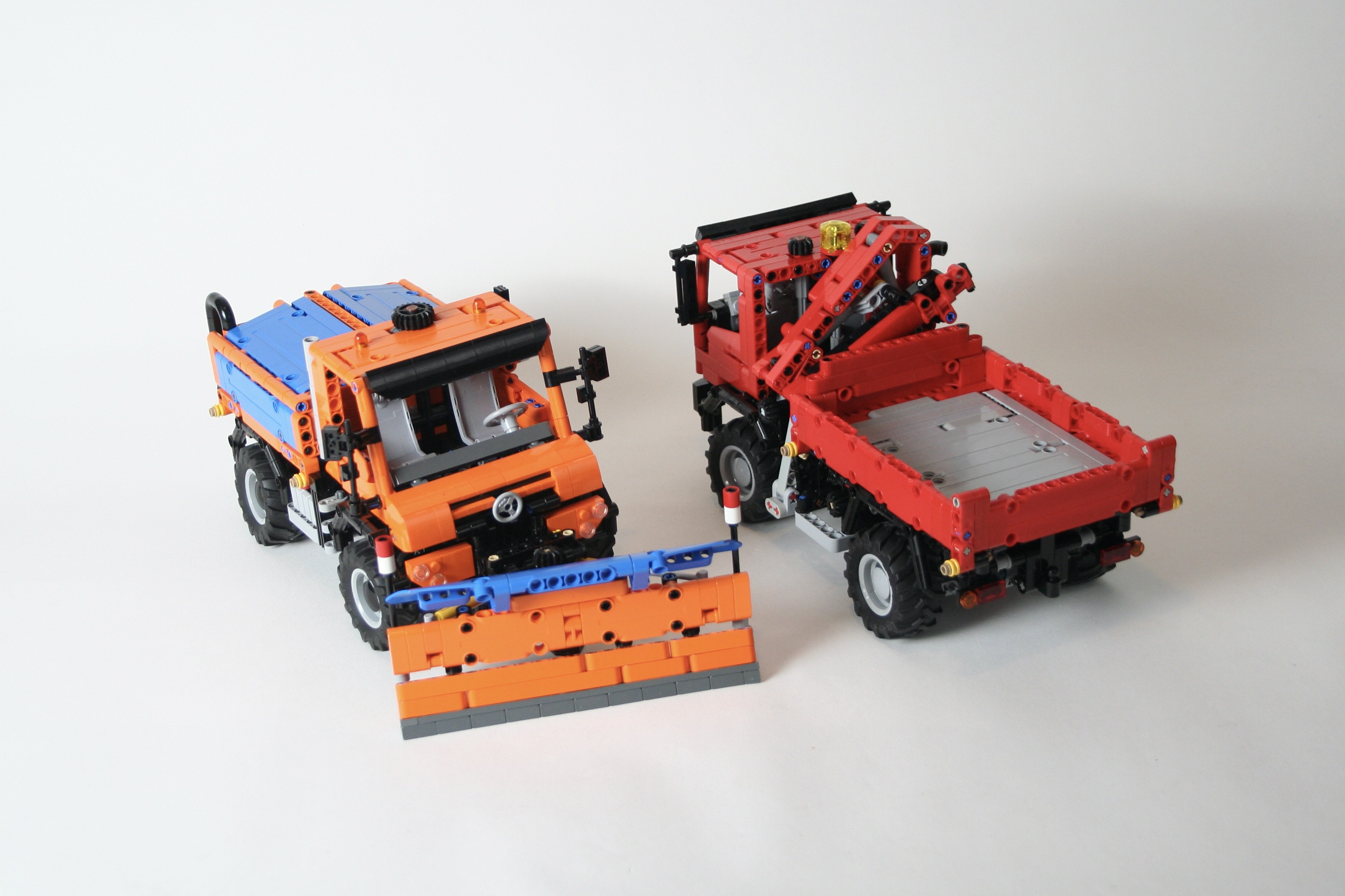
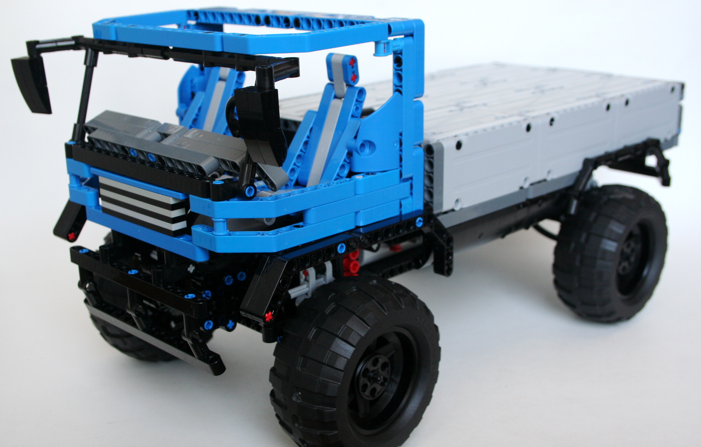
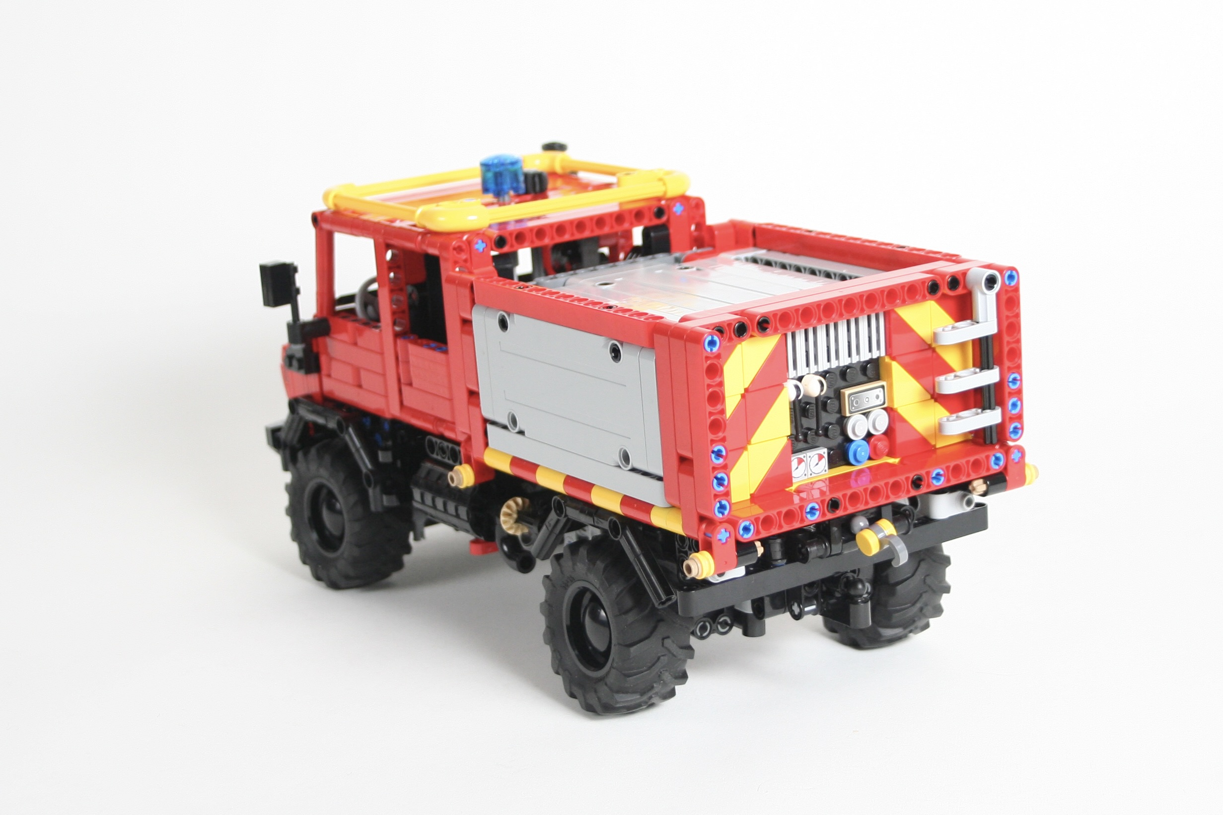
In addition, I wanted some options for bodies, so I created two chassis lengths. The short wheelbase (U4000) has a 19 stud wheelbase, and the long wheelbase (U5000) has a 24 stud wheelbase. Both are similar in design, but have different bed lengths. The U5000 version also allows for both a standard, and four door cab. For the long wheelbase version, I built a fire truck box, and a long bed. For the short wheelbase version, I built a bed and a little camper. The camper features a bathroom, little kitchen, and a table to converts to a bed. Also, plenty of storage compartments are both inside and on the outside of the camper. Finally, a little tipper trailer is available. I built it to match the Dark Bluish Grey U4000, but it can be made in many colors.

I have created instructions for each of these versions, and each can be found at Rebrickable.com: U4000 SWB Truck, U5000 Fire Truck, U5000 LWB Truck, Trailer, Camper.

Just like the U423, I was very happy with how these trucks turned out. The Dark Bluish Grey version is my favorite. The trucks work well, and have all the functions a 1:21 scale truck should. I love all the functions; playing with the winch is great fun! The hood is a little too fragile for my liking, but it looks just like it should. Also, it was a great reason to finally build a camper, and this won’t be the last time. But first, we may need to do another Unimog in 2024. Stay tuned….

Happy Building…

Unimog U423


For my 100th Rebrickable MOC I had to celebrate with a Unimog.

Free Instructions can be found at Rebrickable.com.

So it turns out that I have built a lot of MOCs over the years, and many of them have instructions posted on Rebrickable. Late last year, I recognized I was going to post my 100th MOC on Rebrickable, so I wanted to celebrate the occasion in some meaningful way. After a little thought, it became clear that building another Unimog was the only way to celebrate!

I have build a number of Unimogs over the years, but if one thing has happened during this time, it is the consolidation of the 1:21 scale truck that has become a standard in the LEGO MOC community. LEGO sets like 42098, 42078, and 42128 have helped to standardize the 1:21 scale truck, and many other MOCs have followed suit. Building a Unimog in this scale seemed like a good idea.

I planned right from the beginning that multiple implements would be available for the truck, so the design would need to be able to accommodate each attachment. To support this, a front, rear, and center PTO would be needed, and mounting points on the front, rear, and bed would need to be easily accessible. Once these standards were set, I measured the scale, and made a draft with all the set points fixed. As I built, the steering was finalized as well as the 2 cylinder fake engine. The truck used a rear wheel drive setup, and the rear axle has portal axles and a pendular suspension. Right above the rear axle, I placed a linear actuator to move the tipping bed. After some tinkering, I decided to use a large 36z gear on the left of the truck to move the bed up and down. It is placed just behind the steps, and looks like the left side radiator. Finally, there is a PTO on/off switch on the right of the truck that turns the rear and center PTO on and off.

As I was building the truck, I built the attachments as well, which allowed me to make sure the attachment connection points were ridged, accessible, and standardized. From the beginning I planned on the following attachments: plow, gritter, front winch, rear crane, and bed crane. The front attachments are connected using a 5l axle with stop, and the bed mounts are connected using four 3l axles with stop.

The front plow has worm gear lift and can tilt left and right. Free instructions for the plow may be found here. The rear gritter attaches at the rear and connects to the center PTO gear. When the PTO is turned on, the center auger and the rear spreader both turn. The top of the gritter can open to drop small 1×1 round plates to use as salt. Free instructions for the gritter may be found here.

The front winch and center crane and bed can be easily attached as well. The front winch has a locking mechanism that allows the winch to be locked as needed. The rear bed has a knuckleboom crane that folds up for transportation. Instructions may be found for both here.

Finally, a rear knuckleboom crane is also available. This crane uses the same crane as above, but uses a different attachment point. A small interior cam mechanism that is worm driven is used to connect the rear crane to the truck. Two outriggers are on both sides of the crane and are locked by worm gears as well. The crane folds completely and extends as needed. Again, free instructions for the crane can be found here.

Maybe I will find additional attachments, trailers, and implements for the truck but for now I am done. This project worked just a well as I had hoped and was perfect for my 100th MOC. The truck is just the right size, and has all the features I wanted it to have. The functions work well and integrate with each other well. Each attachment was great addition as well, and gave the truck lots of distinctive styles and looks. I hope you enjoyed the build as well.

Happy building!

Unimog 437


If my previous builds are any indication, I am a big fan of Unimogs. So it was just a matter of time before I built another one. Rather than building one this time, I built a modular system that allows for a number of different versions.

Full instructions can be found here.

This build started with a desired to make another small build with the great Fischertechnik tires I acquired. I wanted to build something small and playful like RM8s FJ or Sheepo’s Defender. As has been happening with many of my recent builds, I wanted to give the MOC some playable options and easy modifications. A Unimog was a perfect option, and who am I to turn down a Unimog? So I gave myself the following constraints: 4×4, I4 fake engine, steering, manual and PF drive options, removable cabs, removable bed, and two chassis. I set off to work.

The axles came together fairly quickly. I decided quickly not to do portal axles, because I wanted the complexity of the MOC to be elsewhere. Both axles have a differential, two soft springs, and are stabilized longitudinally via steering links and laterally via panhard links. All for shocks are mounted on crankshaft parts to get the ride height of the Unimog just right. There is about 1.5 studs of travel for each wheel, which provides adequate articulation.

The axles are connected to a fixed axle that powers a I4 fake motor. Since I wanted the MOC to be easily switched between manual control and PF, the driveline got a little over-complicated quickly. The steering axle and drive axles cross each other twice. This allows for the steering to go to the top for a HOG, and backwards so a PF servo motor can be added. A 16t gear is available at the top of the chassis to power a PTO, or add a PF XL motor to give the Unimog propulsion. The long Chassis can fit a full a full Power Functions pack. When the power pack is not installed lots of open space is available for other additions. I added a three way tipper lift mechanism for both the long and short wheelbase chassis.

Attachment points were added for the rear bed and for the cab. I created three cabs, and each can be added to both chassis (though the Doka looks best on the LWB). Two axles with stop can be pulled to free the cab. I created three beds and a power pack. Four axles with stop are required at each corner to secure the bed. A camper and a crane bed are not far behind on my building queue.

The Unimog turned out exactly as I wanted. The suspension and steering are light and smooth under manual operation, and work great with PF. I am excited about the ability to offer and develop multiple beds and cabs. Instructions are posted, so I look forward to seeing other options people develop to make their own Unimog.

Mack Magma


I consider myself a LEGO purist. I do not cut parts, paint them, and I do very little with custom stickers. But I confess, I’m bending my purist tendencies as of late with all the great custom tire options available. After getting these RC4WD tires, it was time to build another trial truck.

The full gallery may be found on Flickr.

When I build a trial truck, start with three questions: What functions will it have, how many Power Functions receivers will that require, and how many battery boxes will be needed in what placement. Using these decisions I draw up a basic sketch of Power Functions part placement, and I get to work. This truck would have steering, a 2x PF L motor drive, and a two speed transmission. As with other trucks I make, I started with the axles first. The axles were simple as they required no additional functions. Both front and rear have a knob gear in then center, then a 12t to 20t reduction, and a final 8t to 24t reduction in a portal axle setup. The front as a simple steering setup, and the steering universal joints between the first and second gear reduction.

Both axles are strung together with a frame that houses the suspension and electronics. Both axles have pendular suspension, and are linked together with liftarms front to rear. It is a system that is simple, and incredibly effective. A PF M motor is placed in the front to power the steering, and another M motor sits beside it to power the transmission. Two PF IR receivers and two rechargeable battery boxes are placed with one on each side of the chassis. Both PF L motors are mounted side by side in sliding housing in the rear of the chassis. Each motor drives a set of 12t and 16t gear. These separate axles combine to either a 20t or 24t center mounted gear. When both engines are connected 12t to 24t gear, an overall 10:1 ratio is achieved. When both engines are connected to the 16t to 20t gear, an overall 1:6.25 ratio is achieved. With the power of the L motors, this gives a good low ration, and an appropriate high ratio.

As this was a quicker build, I did not spend too much time on the bodywork. A simple flat bed was installed, and the cab is sparse. I selected a simple America style cab from this design idea to build in blue. The grille is big and square, and the rest of the cab generally follows the idea. Both the cab and the bed can be simple removed.

The truck has plenty of power, and the transmission worked without error. The steering was easily controllable. The larger tires gripped very well, as they are soft with big knobs. They were a little taller than LEGO’s tires, and combined with the softer sidewalls, made the truck a little less secure in its footing. But the truck did not roll over easily, and the soft tires made it grip the ground well. I will be using these tires again.

Until the next MOC, happy building.

Unimog U90


About 3 months ago I purchased a set of four Fischertechnik tires from ebricks.ru. After seeing a review of them by RM8, I reached out to him, and he mailed me a set. After a little time, I finally have something to show with them.

Unimog U90

After playing with a number of ideas, I decided to do another Unimog. It’s easy to motivate myself to build a vehicle I love. This time, I wanted to do the unloved U90 (418) version. It was not a terribly successful version, as many find the hood…not one of the best. But few people have built this version, so I was up for it. I put to to a vote on Eurobricks, and the decision was to build it in green. Off I went.

The scale required a 27 stud wheelbase and a 19 stud width. I built the front and rear axles and tied them together. Through a couple of edits, I finally added the suspension and figured out how to get portal axles into the truck. The Power Functions XL motor was mounted just over and in front of the rear axle driving power to all four wheels. The Servo motor was placed directly ahead of the XL for the front axle steering. I added a four cylinder fake engine over the front axle. The rechargeable battery box was placed over the rear axle.

Unimog U90 Driveline

The suspension is a live axle setup, with four hard shock absorbers at each corner. Each wheel has about 2 studs of travel. Not much for a Unimog, but enough for a 418. At this point I started a draft of the cab, and a draft of the bed. At this point the truck had an identity crisis. Move forward with green or find another option.

Unimog U90 Bed Tilt

Building LEGO Technic with green is not the easiest. The color lacks 1×5 and 1×11 beams. Both of the these parts would be needed for the bed and the cab. I could make some things work for the 1×11 in the hood, but there was no other option (read, inexpensive option) for the 1x5s needed for the bed. I toyed with other colors for the bodywork; orange, white, blue, yellow. None of them had the right pop I was looking for. Other than the orange, but, as other have said, orange has been done too many times. Then it dawned on me, “why not use plates?” I had my solution. With one bricklink order, I was done.

The truck drives well, and is easily controllable. The front portal axle can use a little strengthening, so serious trial abilities are lacking with this truck. Both the bed and the cab can be easily removed. I ran out of space for a ram to elevate the bed, but it can tilt three ways. I was pleased with how the truck turned out. It looks great. The driveline coule use some improvements, so I will make those improvements on the next truck.


Kenworth T47


The Kenworth T55 is my favorite Trial Truck I have built. It’s not the best looking, or the most capable, or the most reliable, or even the most popular but it’s the one I keep coming back to. My latest truck is a continuation of the Kenworth series of trial trucks. The T55 would pull a stump, the T47 is quicker, has better steering, and more compliant suspension.

T47

Right from the beginning I knew the truck would have a similar cabin at the T55. It would continue with the four wheel steering, and I added an independent suspension. The dimensions would stay close to the same. From there anything else was fair game. I started with the axles. The new suspensions arms made it a little bit easier to make a good independent design. A CV joint was used at the steering knuckle, which allowed for the steering pivot to be near the wheel. Each wheel had about three studs of travel.

The XL motor was placed on the left of the center line and the rechargeable battery box was placed on the right. A newly acquired Servo Motor was placed rear on the centerline directly in front of the rear axle. I had a little more space left, so I added a simple two speed gearbox. A little more space remained so I added a flat six engine.

T47 Engine

Part of my attraction of the T55 has been it’s coloring, and it’s shape. I wanted to keep the attraction similar, but in a way that would differentiate the trucks. I have been acquiring some green lately, so I thought would be a great color. The cab is basically the same, but now it can tilt so you can work on the engine.

The off road performance was not great on the T55, and the T47 was similar. The independent suspension had too much play at the wheels to be great at steering, and the articulation was not very supple. The truck was great to drive around my house, but when I took it outside it did poorly. The suspension design is better than my last independent set up. There was no slipping of the gears. I think my next design will use the same knuckle, but design a different steering connection. This truck again proves the use of knob wheels rather than a differential for a trial truck. Feel free to make your own, and let me know what improvements you developed.

Happy Building.

Iveco XTR


After a couple of more complex projects it is nice to take a break to do two simpler projects. When I need a little bit of a design rest, I do a trial truck, and usually a fictional one, so I can build as I please.

The full gallery can be found here, and free instructions can be found here.

Iveco XTR

After building a number of trial trucks, I have found some features I like to have on my trucks. Note, these features may be prioritized differently if I was participating in a Truck Trial race. These features I like are linked suspension, PF XL motor for drive, tall clearance, and a center mounted battery box. As I was making this truck for my own pleasure, I forced myself to include all of these features.

I usually start a truck with the axles, and the Iveco was no different. I created the axle with a portal axle build around my favorite piece for both the front and the rear. I also added the space to fit both a differential, or knob wheels for the final drive (though the pictures only show the latter). This would allow me to switch the traction of the truck, and allow for a minor gearing change. While the changeover takes a little bit of time, it’s a nice feature and the gives the truck some versatility. I placed the steering motor directly on the front axle with allowed the middle of the truck to be simplified vastly. In the center of the truck is the battery box mounted longitudinally, and a Power Functions XL motor in the rear. This keeps the heaviest components of the truck in the center and low.

The linked suspension is a setup developed by other that connect two pendualar axles together. Each left side has a linkage that connects the two left wheels together, and the right wheels have the same. This keeps the wheels planted as the pressure from the terrain is balanced across all four wheels. When one wheel has to go up to follow the terrain, the rest of the wheels adjust. It is simple, effective, and keeps the truck a little more planted than a suspension utilizing shock absorbers. Otherwise the truck bounces a little during an obstical.

As you can see in the video, the battery box is getting a little tired, and the snow as a little mushy, but the setup worked well. The truck stayed planted, and it was nice to have two final axle options. It is a simple design that does not require too many hard to find parts, so if you need a good little afternoon project, give the Iveco XTR a build, and tell me what you think.

OK, off to some more complicated builds. Check The Queue. There is some fun stuff coming. Until then, happy building.

Bedford MWD


I have said it before, but my favorite things to build are Trial Trucks.  The combination of the driveline construction, forces on the truck, diversity of body style, and various propulsion systems offered by LEGO combine for a great building experience.  Because of this, I usually am building a Trial Truck, or have one built at all times.  But for some reason, this truck seemed to sit for a long time unfinished.  I struggle with deciding if a truck will be a model of something, or something fictional.  This decision is often made too late in the construction process.  After toying with a Daimler Scout body, I decided I needed to finish this project and the Bedford MWD body was chosen.

The full gallery may be seen here.

01

After some some experience with various designs, I decided to construct a truck around a simple locking differential idea I had recently designed.  Because I would need an extra IR Receiver for the locking function, I decided a simple two speed gearbox (1:6 and 1:10) could use the other IR channel.  I placed all the controls in the middle of the chassis.  The driveline and the steering axle would run through the middle.  On the left side was the Battery Box and the motor for the gear change, and on the right side was the XL drive motor, the gear box, and the motor for the locking differential mechanism.  The steering motor would hang out the back of the chassis over the rear pendular suspension unit.  Both axle were connected by my favorite linked suspension system.

zbedford

Each axle took a little bit of work.  I selected a simple design for the locking differential.  Basically, it is a 24 tooth differential placed directly next to a 24 tooth gear.  A pair of sliding 12 tooth double bevel gears slide back and forth one stud to connect only with the differential, or with both the differential and the neighboring gear locking out the differential.  After toying with some old flex cable, and some pneumatics, I figured I was making it too complicated.  I added a small pivot with a Small Technic Steering Arm, and connected it to a 9L link.  This way both axles could be connected, the suspension and lock could keep operating unaffected by each other, and it all could be controlled by a mini Linear Actuator.

Initial tests were positive, so I then decided to figure out a body for the design.  I worked for too long on a Daimler Scout body.  I had the structure made, but the paneling was just not happening.  After sitting on the project for 5 months, I decided it was time to make something new.  The Bedford design worked well, and helped my get excited again in the project.

Now, once I got outside to drive the truck a glaring problem occurred.  The bevel connection in each axle that transmits the longitudinal drive forces to transversal drive forces kept slipping.  You can hear it in the video.  Because of this, it did not matter if it had locking differentials, or if it had a two speed gearbox, or if it had working suspension.  Anything could stop it.  I though about reworking the axles, but then, I have been working on this for 11 months, it was time to be done.  I’ll use the locking mechanism again.  That worked great.

Thanks for reading.

Mack Marble 5T


I confess.  I took the bait, and started on the 2012 You Design It, We Build It before the final rules had been confirmed.  I should know better.  After all my schooling, you would think I have a good idea about how to follow directions.  The first direction is, wait for directions.  But, with all LEGO building, I enjoy what I am creating, and so even after the rules and directions have been given, I still want to contribute to the LEGO community.  So, my next MOC is another Trial Truck, built with the intention of being easy to play with, easy to build, and tough enough to handle child play.  All with instructions, so you can build one.

See Instruction Page

I built this model based on what I thought could be improved on set 9398.  While this new set was a great step forward for the LEGO company, I felt there where a couple of changes that should be made to make the model a better off-roader.  Because I was working with the assumption that this would be something LEGO would produce, I gave myself a couple of constraints.  First, the model had to be less than, or equal to, the cost of 9398.  Second, the model had to have improved off-roading skills.  Third, the model had to have easy playablity, so the drivetrain had to be reliable, the battery should be easy removable, and it should be easy to drive.

I started the frame before the axles.  I placed the battery box directly over the driveshaft.  An XL motor was place behind the BB and three 16z gears above the driveshaft.  One 16z gear went up to the fake motor shaft.  The driveshaft would connect front and rear to the two axles through the new ball joints from 8110.

I then built the two axles, starting with the rear.  To keep the speed of the Mack similar to the 9398, I would gear down the XL motor to about 1:4.  The driveshaft came out of the ball joints and connected to the differential.  I chose two 12z/20z gear sets as the final reduction.  This would keep the driveline a little stronger, and help keep various axles from working their way out of the gears, much like the design of the 9398.  The final gearing was 1:3.89.  It’s not a stump puller, but it could still move up most hills.

The front axle was a little more tricky.  Basically, it had a similar setup, with a PF M motor placed on in it to work the steering.  This was by design.  To keep the driveline reliable, and limit the failure of steering, I kept the steering part of the axle, rather then having components placed in the chassis, and then connected via a shaft to the front axle.  The steering is a little quick for my liking, but it works flawlessly.  To understand more about the axles, check out the instructions.

Through a little trial and error, I connected the suspension, and tweaked it so it would function in a way that was robust, and allow for great movement.  I am still not pleased with how it turned out aesthetically  but it functioned without problems, it supported the model well, and allowed for sufficient articulation, so I left it.

I then added a simple body, a basic rear bed, and added some engine components such as exhaust,  intake, and a simple turbocharger behind the fake motor.  When I was done, I noticed the cab looked a little like an old Unimog.  This seems to be a theme with me, as I love the look of the Unimog.  On the other hand, I do not like the look of too many cabover truck designs, as such, many of my trucks have the slight setback cabover design that is very similar to the Unimog.  My T55 is like this, and this is why I have built so many Unimogs.

The model worked well.  the suspension and stability was perfect.  The truck was stable, and did not roll over, all while being able to handle various terrains.  The gearing was sufficient and would be great for a playing child.  It was easy to change out the 12z/20z gears in the portal axles to a 8z/24z setup which made the truck a little more strong.

It would be a great model for many LEGO fans due to cost, reliability  stability, and playability.  So I have posted instructions for people to enjoy the model as well.  I think it would have been a great LEGO set, then the rules were released.

Next time I’ll wait for the rules.  Thanks for reading.

Full gallery is here.

International FTTS


It has been a little quiet in Thirdwiggville for the last month.  I have been working on a project that is taking a lot of time and resources, so my posts have slowed, even though my building has not.  But just wait, it’s going to be awesome.

Last summer I wanted to do another Trial Truck that would utilized some features I have never used before.  I wanted something complicated to see how it would work.  I wanted a model that would use four wheels steering, independent suspension, and have a simple two speed gearbox while being low to the ground.  After spending some time at the Chicago Autoshow, I saw a FTTS concept, so I thought this would be a great vehicle to model for this next truck.

This model would be built around an independent suspension.  After seeing it used so effectively in a truck by ATRX, I wanted to give it a try.  Each of the four wheels would use a simple double a-arm set-up with a wheel mount attached at the outside.  The wheel mount would house the portal axle and connect the steering linkage.  After a couple of different designs, I also decided the wheel mount would also connect the the shock absorbers.  This was a little unorthodox, as most independent designs mount the shock absorbers directly from the frame to the a-arms.  I did this for two reasons.  First, the model would be heavy, and I could not get the support I needed when the shocks were connected to the a-arms.  Second, and most importantly, I noticed too much suspension flex when the shocks were mounted to the a-arms.  The force applied to the wheel would go up the wheel, to the wheel mount, through the pivot, halfway down the lower a-arm to the shock.  LEGO is relatively stiff, but all these steps complied too much flex.  I would not have it.  I mounted the shocks on the wheel mount, and created a simple MacPherson strut set-up.  This worked well, as it allowed for full steering movement, long suspension travel, and adequate support of the truck.

The front and rear suspension axles both had a PF-M motor driving the steering.  Each were on independent PF channels connected to a single 8878 Battery Box to allow for individual steering, crab steering, and to solve steering drift commonly problematic with four wheels steering vehicles.  Both axles were connected with dual drive shafts running the length of the truck.  One drive shaft would then connect through a simple two speed gearbox to the PF-XL motor.  The final gearing was 1:6.2 and 1:10 for the truck.  This gave the truck sufficient top speed, with an effective crawler gear.  The Battery Box used for the drive motor and the gear shift motor was placed directly behind the front suspension, and in front of the drive motor.  This placement was perfect for stability.  It helped give great traction to the front wheels, kept the center of mass low and to the center with a slight forward bias.

I then finalized the model with a simple removable body built on a Technic frame.  While the hood was little high, and the rear body a little too short, it looked pretty close to the rear FTTS.  Fans seems to like the look, as it is still one of my more popular model.  See the full gallery here and the Work in Progress gallery here.

The model was a lot of fun to drive, and due to its squat design, it was very well planted.  The truck did not want to role over.  I think it could have used a little more suspension travel, and having four wheel steering was crucial to give it some maneuverability that was lost due to the suspension design.  The gearbox was flawless.  The truck did have some trouble skipping gears at the portal axle.  It seemed to happen when a single wheel was over-stressed as the driveshaft could have used stronger bracing in each suspension unit.  This placed a lot of strain on the particular wheel.  So would I do the independent suspension again.  Maybe, but it would need some strengthening and redesign.  Maybe it’s time for another truck like this.

Thanks for reading.  Something big is coming.