Mack Magma


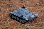
I consider myself a LEGO purist. I do not cut parts, paint them, and I do very little with custom stickers. But I confess, I’m bending my purist tendencies as of late with all the great custom tire options available. After getting these RC4WD tires, it was time to build another trial truck.

The full gallery may be found on Flickr.

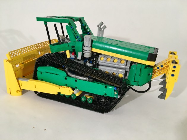
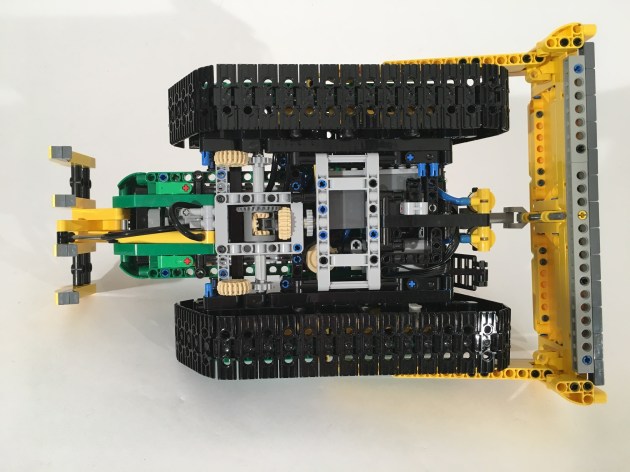
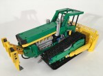
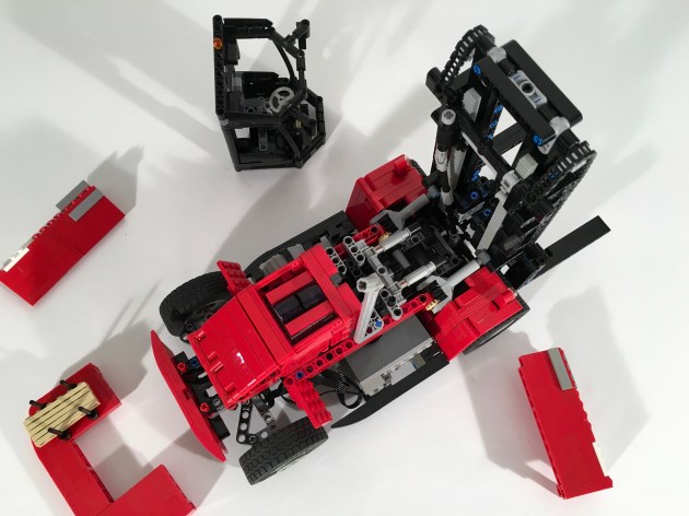
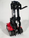
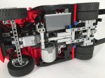
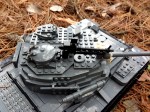
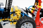
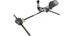
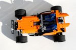
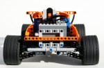
When I build a trial truck, start with three questions: What functions will it have, how many Power Functions receivers will that require, and how many battery boxes will be needed in what placement. Using these decisions I draw up a basic sketch of Power Functions part placement, and I get to work. This truck would have steering, a 2x PF L motor drive, and a two speed transmission. As with other trucks I make, I started with the axles first. The axles were simple as they required no additional functions. Both front and rear have a knob gear in then center, then a 12t to 20t reduction, and a final 8t to 24t reduction in a portal axle setup. The front as a simple steering setup, and the steering universal joints between the first and second gear reduction.

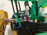
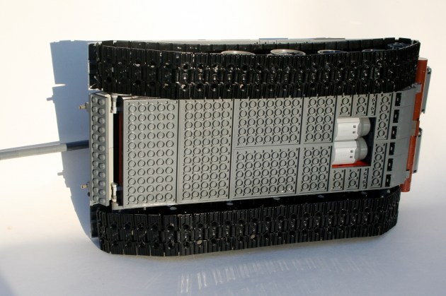
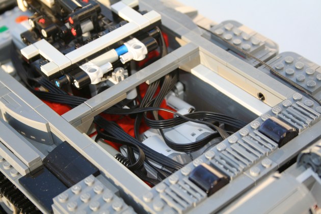
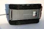
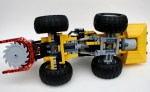
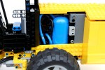
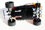
Both axles are strung together with a frame that houses the suspension and electronics. Both axles have pendular suspension, and are linked together with liftarms front to rear. It is a system that is simple, and incredibly effective. A PF M motor is placed in the front to power the steering, and another M motor sits beside it to power the transmission. Two PF IR receivers and two rechargeable battery boxes are placed with one on each side of the chassis. Both PF L motors are mounted side by side in sliding housing in the rear of the chassis. Each motor drives a set of 12t and 16t gear. These separate axles combine to either a 20t or 24t center mounted gear. When both engines are connected 12t to 24t gear, an overall 10:1 ratio is achieved. When both engines are connected to the 16t to 20t gear, an overall 1:6.25 ratio is achieved. With the power of the L motors, this gives a good low ration, and an appropriate high ratio.

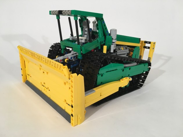
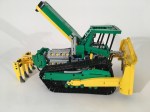
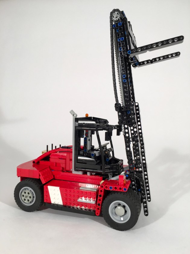
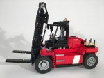
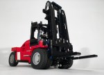
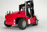
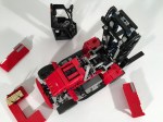
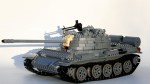
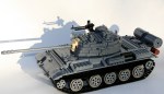
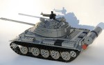
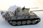
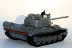
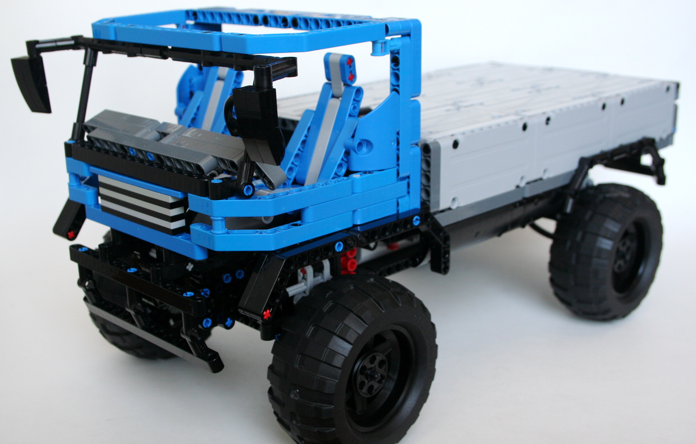
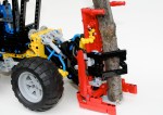
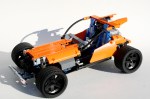
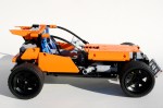
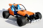
As this was a quicker build, I did not spend too much time on the bodywork. A simple flat bed was installed, and the cab is sparse. I selected a simple America style cab from this design idea to build in blue. The grille is big and square, and the rest of the cab generally follows the idea. Both the cab and the bed can be simple removed.

The truck has plenty of power, and the transmission worked without error. The steering was easily controllable. The larger tires gripped very well, as they are soft with big knobs. They were a little taller than LEGO’s tires, and combined with the softer sidewalls, made the truck a little less secure in its footing. But the truck did not roll over easily, and the soft tires made it grip the ground well. I will be using these tires again.

Until the next MOC, happy building.

Advertisement

Concept John Deere Bulldozer


In what is becoming a little bit of a theme, I submitted another design for a Lego contest. In the long line of Eurobricks.com contests, the Technic Challenge 10 called for a pneumatic build. Challenge accepted!

Full Gallery Here

Concept John Deere Bulldozer Left

The contest had very few constraints other than the build had to use Pneumatics. As I have mentioned before, working with pneumatics is not my preference. I don’t like them, so it was good for me to step out of my comfort zone.

I was feeling especially creative this time, so I thought about a number of concept ideas. Pneumatics do not tend to work smoothly when lifting arms so I decided against an excavator and a loader early. Additionally, I was not willing to invest in additional parts for this project. After a couple of drafts, the idea of this bulldozer was born. Taking some inspiration from some of John Pope’s design, the basic idea was there. The dozer would have different tracks, a three movement blade, a crazy engine, and a forward thinking design.

Concept John Deere Bulldozer Blade

I started with the tracks. After moving the axle points four wheels countless times, I came up with a design I liked. I made another one, and linked them together. The I worked on the blade. The dozer would have a lift, tilt, and side to side angle adjustment. After playing around with some idea, I found a solution I liked. Two pneumatic rams were on the front to lift the blade on the top. Then two links were connected low on the two sides of the blade, and then on each side of the dozer. These points on the dozer were moved fore and aft by on pneumatic ram each. These side rams would move the blade left or right individually, or together they would tilt the blade up or down. Additionally, it allowed all the tubing to be internal.

Concept John Deere Bulldozer Open

I added a small compressor powered by a Power Functions M motor, and the battery box under the cab, and added the 16 cylinder engine (coupled V-8 and Flat 8). The cab was easy to get the shape I wanted, and gave me some space for another pneumatic ram to open the hood. I then decided to add a ripper since I had one pnuematic left. The new 1×11 ram a great addition, but a little more power could have been used for the ripper.

Concept John Deere Bulldozer Chassis

I was pleased with the look the bulldozer. The functions worked well, but on reflection, the were not exciting enough to be competitive for a contest. After two pneumatic builds in a row, I find some of the frustrations I have with them remain, but I am discovering some charms as well. We’ll see what comes next.

Happy building.

Kalmar DCG180-9


After doing a lot of non powered builds, it was time for me to do something motorized. I very much enjoyed doing a forklift a couple of years ago, so it was time for another one.

See the full gallery on Flickr and Brickshelf.

Kalmar 180

The JCB930 that I did a couple of years ago was non-motorized and had some great features. I wanted to build something with all the same features, and since I would need more room for all the electronics, I decided early to model the forklift after the Kalmar mid-sized 180 model. The model would have drive, steering, a two stage lift, and fork tilt. I did not realize how hard this would be. I wanted to keep the  boom clear for visibility, and the forks not more than two studs in front of the wheels to keep integrity of scale.

Kalmar 180 Front

I set the scale and I went to work. After setting the chassis measurements, I went to work on the fork and boom. I knew I wanted to have a two stage boom, and I wanted to keep as much of the boom open as I could. The forks connect through the middle of both the first and second stage booms, and pinch both together. The middle boom is has a gear rack on both sides to lift the forks. This boom has two gears at the top, to route the chain over the top to move the forks. The outer boom is connected to the chassis at the bottom, and two mLA connect to it operate the tilt. After some working, I was able to get the boom to be thin, and just how I wanted.

Kalmar 180 Up

I decided early that I want to keep the motors out of the boom. So I had to route the lifting function out to the forklift body through the bottom pivot. This required routing the lifting axle under the drive differential. The lifting axle then move rearward, and connected up to a PF L motor. On top of the lifting axle was the drive axle. The PF XL motors was mounted transversally on the right side, and drove and axle forward to connect directly to the differential. To give me some additional space at the front, a portal axle was mounted on its side to move the differential rearward. A PF Servo was mounted in the rear, over the steering axle, and drove the steering function. The steering uses some 2×4 liftarms mounted at an angle to allow for a better steering angle. Finally, a PF M was mounted in front of the Servo, under the cabin to drive the tilt function. None of the mechanics were difficult, but the packaging required a number of drafts.

Kalmar 180 Open

The final hurdle was the body work. I spend a lot of time early in my MOCs working on packaging placement, so I do not have many body work problems later in the build. Still, some simple SNOT work was needed on the side sills to fit about the battery box, and the XL motor. Oh, and the wires. The cab was pretty straightforward, but still took a little bit of time. Finally, I had some trouble with the rear engine cover and counterweight. In the end it was a simple design that I settled on, but I tried many designs. Again, this took a lot of time.

It took a long time, but I am pleased with the final product. The functions worked smoothly and consistently. The control that was afforded by the fork functions was great. It could lift three AA battery boxes at a time. The steering was quick, and had a great lock which gave great maneuverability. The XL motor provided adequate power, and moved the forklift well. Finally, the bodywork represented the original Kalmar well. I hope you enjoyed as well.

Until next time, Happy Building.

T-55A


The T-72 that a made a couple of years ago is still the most popular MOC I have made; at least in terms of internet analytics. This year, I committed to making another tank, so I figured keeping in line with old Soviet armor would be rather apropos.

The main gallery may be found on Brickshelf or at Flickr. Instructions may be found here.

T-55

The T-54/T-55 line of tanks have been produced in greater numbers than any other tank. The MOC represented here is a T-55A, representing types that were assembled starting in 1970. This series included an updated NBC and antiradiation system, an upgraded engine, and also added back in the 12.7mm anti-aircraft DShK on the loader’s hatch that was part of the original T-54 spec.

As with most of my MOCs, I starting scaling the tank before any building took place. I knew I wanted to use the newer, larger track links, and I knew I wanted to use the old mid-sized wheels. This set my scale, so I got to work. Starting with the chassis and the hull I worked first on the driveline and suspension. I used simple 2×4 liftarms to connect the road wheels to a suspension axle which activated a shock absorber inside the hull. Each road wheel has its own shock absorber. Fitting them all in took some creativity, but they are all mounted inside on the left and right sides of the hull. In the end, each wheel has about 3 studs of vertical travel.

T-55 Chassis

In between each suspension bank are the remaining mechanics.  After the suspension was set, I worked on the turret functions. Right from the beginning, I knew the tank would have a rotating turret and an elevating gun. It was clear having the elevation mechanics for the gun in the turret would be tight, so I decided instead to have the functions placed in the hull rather than in the turret. Using a vertically mounted mLA, connected directly to the breach of the gun, I was able to develop a method that would elevate the gun throughout the full turret rotation. The turret rotation was driven by a 8z gear connected to the turntable, and reduced by a worm gear. Both motors for the elevation and rotation are placed directly in front of the turret.

T-55 MechBehind the turret are two PF L motors mounted transversely side by side. They drive a 1:1 gearbox which connect directly to each rear drive sprocket. The IR receivers are placed above the gearbox. For those keeping score at home, the internals are (f to r) the battery box, the turret motors, the turret mechanics, the drive motors, and finally the IR receivers.

Working on the exterior of the MOC is what took the most time. The hull came together pretty quickly, with the exception of the details over each track. Most of the finishing time came with the turret exterior. Most Soviet tanks have the distinctive mushroom turret, which considering LEGO’s cube orientation presented some challenges. The turret of the T-55 also has a slight triangle orientation when viewed from the top. Like the T-72, I designed the turret with four side orientations (left, right, front, and rear), and one top orientation. Starting from the rear, I added a basic curved structure. The sides each had a couple levels of slopes, each tapering in toward the gun. The front was a little more complex. There are two “slope blocks” made of 4 curved slope bricks, and a supporting structure. One slope block is mounted on each side of the gun. The support structure is a mess of bricks with a stud on one side, headlight bricks, and plates. The top of the turret is plates on the front, and two sloped plate sections under each hatch. The two hatches are mounted to the turret support under the sloped plate sections. The AA machine gun is placed on the top, and various external mountings are placed in various ways around the turret.

T-55 Turret Detail

After making a lot of non-powered MOCs, it was nice to get back into Power Functions. I was pleased that everything worked flawlessly. The drive had adequate traction and power. The suspension worked well, and provided good floatation and travel. The turret rotation was smooth and allowed for precise directions changes. The gun elevation worked great, though I had to limit turret rotations to under four before the clutch on the mLA would snap. After a number of smaller builds, and frustratingly long builds, I was nice to finish something that worked well, provided constant entertainment throughout the build, and turned out quite nice.

Happy building.

Hawker Typhoon MkIb


Two years ago I built the Spitfire MkIIa. It remains one of my more popular builds, and one of which I am still quite proud. It was not my first large plane, though when I completed it, I said it would be my last.

As my father would say, “never say never.”

Typhoon

The full gallery may be seen here.

I learned a lot of great things from the Spitfire. Large scale building is exciting, and challenging in that you have to think about significant structural considerations, placement, and shaping before and while your build.

With this in mind, I wanted to develop what I have learned, but allow myself the ability to take a large scale aircraft to the next level. I wanted to improve the function of the control surfaces, design my own propellor, use four Power Function channels, and use the boatload of Dark Green parts that I had recently acquired. I considered a number of airplanes, including doing the FW-190 again, but I finally settled on the Typhoon. Time to get building.

After some planning, I had my scale. 1/13 was an appropriate size for me to replicate the plane and its functions, while still keeping the plane from getting too large. This scale would also allow for LEGO wheels for the landing gear, and a worker able propellor spinner design. As I learned from the Spitfire, placement of large components needed to be done early, and placed in the MOC to its exact final location. As the structure of the fuselage and wings would be stressed heavily, large components could not get in the way. Once I placed the engine block, the landing gear, the power functions, and the control surfaces, I was able to start putting together the robust structures that would support the final plane. One of the major challenges of this plane was the outset landing gear on the wings. Because they were located 42 studs apart, the wings needed to be strong. But due the the space taken for the control surfaces, and the massive 24 cylinder power pack, the wings still sag a little under load.

The control surfaces were activated with strings with studs on each end. I found this to be a better system than the axle controls for the Spitfire. It kept the controls more smooth, and reduced the amount of play in the controls. The elevator and ailerons were controlled with the joystick, and the rudder was controlled by two foot pedals in the cockpit. The remaining functions were controlled via Power Functions. An XL motor powered the massive 38 stud diameter propellor, as well at the 24 cylinder Napier Sabre engine. A M motor controlled the pitch of the propellor. Another M motor powered the landing gear, and still another  adjusted the flaps. All four motor were mounted in the chin of the aircraft; I had to use that huge chin for something. The two IR receivers were mounted in under the windscreen, and the rechargeable battery was mounted behind the cockpit.

Finally, I had to make sure all the markings were accurate. Again, due the limits of dark green parts, it was not an easy task. I started with wings, and made sure to add invasion stripes, and work my way out to the tips. The roundels were a little different than the Spitfire, but were a little larger. The fuselage took a little work to make sure the panels could be easily removed, but I eventually got there. The fuselage roundel should have a yellow ring around the outside, but the strip is so small, I could not figure out a good way to do it.

The plane worked almost perfectly. The ailerons were a little sticky, but other wise everything else managed to work for an 8 hour shift at Brickworld. The plane was liked enough to be nominated for Best Air Ship. While it did not win, it was validation that the the model was a success.

Happy Building.

Iveco XTR


After a couple of more complex projects it is nice to take a break to do two simpler projects. When I need a little bit of a design rest, I do a trial truck, and usually a fictional one, so I can build as I please.

The full gallery can be found here, and free instructions can be found here.

Iveco XTR

After building a number of trial trucks, I have found some features I like to have on my trucks. Note, these features may be prioritized differently if I was participating in a Truck Trial race. These features I like are linked suspension, PF XL motor for drive, tall clearance, and a center mounted battery box. As I was making this truck for my own pleasure, I forced myself to include all of these features.

I usually start a truck with the axles, and the Iveco was no different. I created the axle with a portal axle build around my favorite piece for both the front and the rear. I also added the space to fit both a differential, or knob wheels for the final drive (though the pictures only show the latter). This would allow me to switch the traction of the truck, and allow for a minor gearing change. While the changeover takes a little bit of time, it’s a nice feature and the gives the truck some versatility. I placed the steering motor directly on the front axle with allowed the middle of the truck to be simplified vastly. In the center of the truck is the battery box mounted longitudinally, and a Power Functions XL motor in the rear. This keeps the heaviest components of the truck in the center and low.

The linked suspension is a setup developed by other that connect two pendualar axles together. Each left side has a linkage that connects the two left wheels together, and the right wheels have the same. This keeps the wheels planted as the pressure from the terrain is balanced across all four wheels. When one wheel has to go up to follow the terrain, the rest of the wheels adjust. It is simple, effective, and keeps the truck a little more planted than a suspension utilizing shock absorbers. Otherwise the truck bounces a little during an obstical.

As you can see in the video, the battery box is getting a little tired, and the snow as a little mushy, but the setup worked well. The truck stayed planted, and it was nice to have two final axle options. It is a simple design that does not require too many hard to find parts, so if you need a good little afternoon project, give the Iveco XTR a build, and tell me what you think.

OK, off to some more complicated builds. Check The Queue. There is some fun stuff coming. Until then, happy building.

T-72 Instructions


It’s going to be a busy week in thirdwiggville. Before everything goes live, I thought it would be fun to let everyone know I have completed instructions for my T-72. I don’t know what took me so long. If you want to make a copy for yourself, you can for $5.   Buy Now Button

T-72

Otherwise, stay tuned.

Bedford MWD


I have said it before, but my favorite things to build are Trial Trucks.  The combination of the driveline construction, forces on the truck, diversity of body style, and various propulsion systems offered by LEGO combine for a great building experience.  Because of this, I usually am building a Trial Truck, or have one built at all times.  But for some reason, this truck seemed to sit for a long time unfinished.  I struggle with deciding if a truck will be a model of something, or something fictional.  This decision is often made too late in the construction process.  After toying with a Daimler Scout body, I decided I needed to finish this project and the Bedford MWD body was chosen.

The full gallery may be seen here.

01

After some some experience with various designs, I decided to construct a truck around a simple locking differential idea I had recently designed.  Because I would need an extra IR Receiver for the locking function, I decided a simple two speed gearbox (1:6 and 1:10) could use the other IR channel.  I placed all the controls in the middle of the chassis.  The driveline and the steering axle would run through the middle.  On the left side was the Battery Box and the motor for the gear change, and on the right side was the XL drive motor, the gear box, and the motor for the locking differential mechanism.  The steering motor would hang out the back of the chassis over the rear pendular suspension unit.  Both axle were connected by my favorite linked suspension system.

zbedford

Each axle took a little bit of work.  I selected a simple design for the locking differential.  Basically, it is a 24 tooth differential placed directly next to a 24 tooth gear.  A pair of sliding 12 tooth double bevel gears slide back and forth one stud to connect only with the differential, or with both the differential and the neighboring gear locking out the differential.  After toying with some old flex cable, and some pneumatics, I figured I was making it too complicated.  I added a small pivot with a Small Technic Steering Arm, and connected it to a 9L link.  This way both axles could be connected, the suspension and lock could keep operating unaffected by each other, and it all could be controlled by a mini Linear Actuator.

Initial tests were positive, so I then decided to figure out a body for the design.  I worked for too long on a Daimler Scout body.  I had the structure made, but the paneling was just not happening.  After sitting on the project for 5 months, I decided it was time to make something new.  The Bedford design worked well, and helped my get excited again in the project.

Now, once I got outside to drive the truck a glaring problem occurred.  The bevel connection in each axle that transmits the longitudinal drive forces to transversal drive forces kept slipping.  You can hear it in the video.  Because of this, it did not matter if it had locking differentials, or if it had a two speed gearbox, or if it had working suspension.  Anything could stop it.  I though about reworking the axles, but then, I have been working on this for 11 months, it was time to be done.  I’ll use the locking mechanism again.  That worked great.

Thanks for reading.

CAT 573C Feller


LEGO takes up space.  We all know this, and yet we still seem to try to cram as many working functions into a MOC as we can.  Sometimes it works out well.  Sometimes we have to scrap a few functions.  Other times, the functions are so dense you really cannot believe you got it to work.  This is the story of my wheeled feller.

The full Gallery may be found here. Instructions may be purchased for $5 USD.  Buy Now Button

CAT 573c Feller

I have been thinking about making a feller for about two years now.  It is a project I have never seen done before, with the exception of two tracked fellers (OK, and my other one).  Over this time, I have been planning, acquiring parts, and making plans, and over the last four months I have been building.  Nothing I have made has been so complicated or so dense.  There is no space left.

As I always do, I stared with the dimensions of the vehicle.  The schematics for the CAT 573C were easily available, so I stared with the chassis.  I knew space would be an issues, so the driveline had to be simple and compact.  The Power Functions XL motor would be geared down 3:1 and mounted just behind the rear axle.  A drive shaft would move through the steering pivot to the front axle.  The rear axle would have simple pendular suspension.  The steering would be completed by two linear actuators placed on either side of the pivot with a PF M motor on top.  Simple enough.

From here, things got complicated quickly.  The MOC would have four remaining functions.  The feller saw, the grapple arms, the feller tilt, and the feller lift.  Since trees are rather heavy, fellers are designed with as many of the system mechanics behind the rear axle.  As such, all of the functions I would add would need to be in the rear, as the front would not have any space.  I quickly learned this would not work.

Eventually, I found what would fit.  The IR Receivers would make up the rear bumper, and the battery box would be directly over them, off to the left.  Two PF Ms would be on the right and would drive two mini Linear Actuators.  These would move two pneumatic valves. These pneumatics would move the lift function and the grapple arms function.  An air tank would supply the pressure from a pneumatic pump placed on the driveline.  Another PF M would be placed over the front axle to give the feller head the tilt functions (it should be noted, 7 designs, and five weeks were spent on this feature alone).  The final PF M was in the feller head, and would drive the feller saw.

After packing, repacking, and packing again, all the features we set.  Then all the cabling and hosing were placed.  No easy task, as I was running out of space, and 25 or so hoses, and 10 cables take up a lot of room.  I added some comfort features to the cable, including a (half) chair and a roll cage.  And so Mr. Technic could get in, a little step.  Then a lot of paneling for the rear, including some access doors on the rear, and the model was done.  Here it is in action.

As you can see in the video, the MOC worked well, but some of the functions did not work as clean as I would have liked.  The drive and steering were fine, with an easy drivability.  There was a lot of mass in the back, so sometimes the torque from the drive motor would cause the back to tip.  The saw worked well enough, and for the most part so did the tilt, but the pneumatic lift struggled.  It was a little overloaded because the saw unit was too heavy.  The grapple arm worked well, but for both pneumatic rams were hard to control.  As always with LEGO pneumatics, they too often are off or on.

Until the next MOC, happy building.

Talon Track


Every once and a while I see something so creative I have to build something like it.  I happened with my HH-65.  It happened with my Zil 132.  And to some extent it happened with my Spitfire.  But when I saw the Urban Buggy from Chrismo, I though I have to make something like it.  It was such a fresh and creative design.  It had such great lines, a perfect stance, and a unique driveline setup.  But while imitation and outright plagiarism are the most sincere forms of flattery, I thought something of my own design would be a better contribution to the LEGO community.  I present my Talon Track Car.

You may find the full gallery here, and the instructions here.

I designed this car to be fast and stable, just like a track car.  I started with a drivetrain that would be reliable and effective.  A PF XL for drive, and a PF M for the steering.  I placed the PF M in the front mounted directly on the suspension unit, with a return to center spring in the middle of the mount.  The system is set up differently than in my Rumble Bee, but uses the same return part.  Each suspension arm would have a single shock absorber.  Directly behind the steering motor was the XL for the drive.  It was geared up with a 20z/12z ratio, with the driveshaft connecting directly to the 20z gear that turned the differential.  The rear suspension used an independent setup that was developed a long time ago for my Red Car Bigger (great name, huh).  If it’s not broke, don’t fix it.  The suspension was planted.  I placed the rechargeable battery box and the IR receiver behind the rear axle.

The car was quick, and didn’t have any problems, but faster would have been cool.  The return to center system worked well, especially for the quickness of the car, and the quickness of the steering.  It was easy to control.  The car was robust, and crashed well.  So go ahead and build your own.  Enjoy.