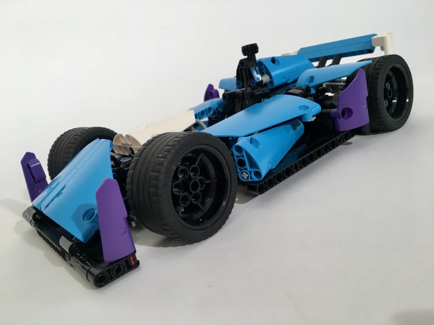
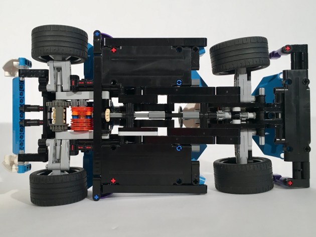
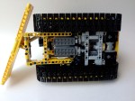
After the introduction of the 3T Sports Sedan and the 2C Sports Car, Thirdwigg Motors was ready to start exploring the electrification of vehicles. Since the previous vehicles all had internal combustion, in order to more into electrification, some testing was required. The car features a single electric motor just forward of the rear axle. Geared up 3:1, the motor provides sufficient acceleration and top speed.
Since this is track car suspension and bodywork are crucial for performance. The flat bottom of the car contributes to downforce, as does the rear wing and aerodynamic bodywork. The front and rear suspension is independent with torsen bars at each corner. There is very little wheel travel, appropriate for a track car. Steering is handed with the steering wheel, and the HOG just above the driver’s head.
The car was a good exercise to test a different drive mode in a LEGO car. Another electric car will soon be coming from Thirdwigg Motors, so this test vehicle was a good first step. The suspension was a little soft; it worked OK which was my experience with the Octan F1 as well. Frankly, the torsen system only works great for tanks in my experience, but maybe with a little work, it can have an application in future cars.
In what is becoming a little bit of a theme, I submitted another design for a Lego contest. In the long line of Eurobricks.com contests, the Technic Challenge 10 called for a pneumatic build. Challenge accepted!
The contest had very few constraints other than the build had to use Pneumatics. As I have mentioned before, working with pneumatics is not my preference. I don’t like them, so it was good for me to step out of my comfort zone.
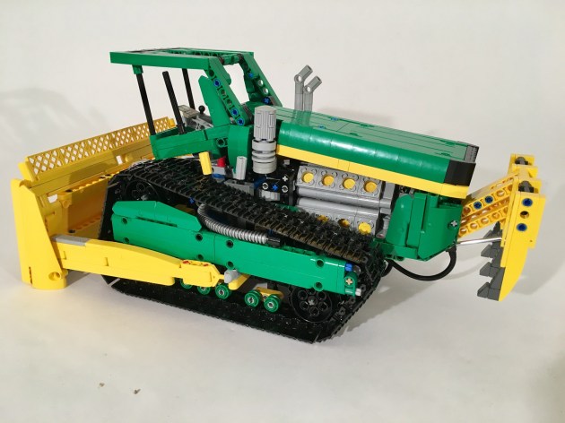
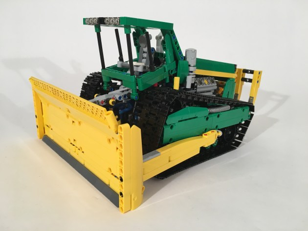
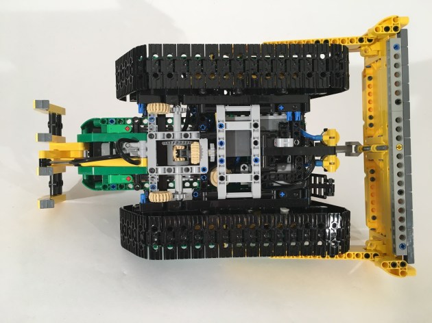
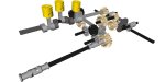
I was feeling especially creative this time, so I thought about a number of concept ideas. Pneumatics do not tend to work smoothly when lifting arms so I decided against an excavator and a loader early. Additionally, I was not willing to invest in additional parts for this project. After a couple of drafts, the idea of this bulldozer was born. Taking some inspiration from some of John Pope’s design, the basic idea was there. The dozer would have different tracks, a three movement blade, a crazy engine, and a forward thinking design.
I started with the tracks. After moving the axle points four wheels countless times, I came up with a design I liked. I made another one, and linked them together. The I worked on the blade. The dozer would have a lift, tilt, and side to side angle adjustment. After playing around with some idea, I found a solution I liked. Two pneumatic rams were on the front to lift the blade on the top. Then two links were connected low on the two sides of the blade, and then on each side of the dozer. These points on the dozer were moved fore and aft by on pneumatic ram each. These side rams would move the blade left or right individually, or together they would tilt the blade up or down. Additionally, it allowed all the tubing to be internal.
I added a small compressor powered by a Power Functions M motor, and the battery box under the cab, and added the 16 cylinder engine (coupled V-8 and Flat 8). The cab was easy to get the shape I wanted, and gave me some space for another pneumatic ram to open the hood. I then decided to add a ripper since I had one pnuematic left. The new 1×11 ram a great addition, but a little more power could have been used for the ripper.
I was pleased with the look the bulldozer. The functions worked well, but on reflection, the were not exciting enough to be competitive for a contest. After two pneumatic builds in a row, I find some of the frustrations I have with them remain, but I am discovering some charms as well. We’ll see what comes next.
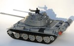
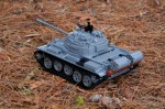
The T-72 that a made a couple of years ago is still the most popular MOC I have made; at least in terms of internet analytics. This year, I committed to making another tank, so I figured keeping in line with old Soviet armor would be rather apropos.
The main gallery may be found on Brickshelf or at Flickr. Instructions may be found here.
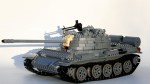
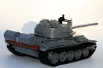
The T-54/T-55 line of tanks have been produced in greater numbers than any other tank. The MOC represented here is a T-55A, representing types that were assembled starting in 1970. This series included an updated NBC and antiradiation system, an upgraded engine, and also added back in the 12.7mm anti-aircraft DShK on the loader’s hatch that was part of the original T-54 spec.
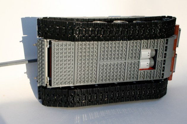
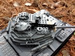
As with most of my MOCs, I starting scaling the tank before any building took place. I knew I wanted to use the newer, larger track links, and I knew I wanted to use the old mid-sized wheels. This set my scale, so I got to work. Starting with the chassis and the hull I worked first on the driveline and suspension. I used simple 2×4 liftarms to connect the road wheels to a suspension axle which activated a shock absorber inside the hull. Each road wheel has its own shock absorber. Fitting them all in took some creativity, but they are all mounted inside on the left and right sides of the hull. In the end, each wheel has about 3 studs of vertical travel.
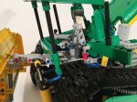
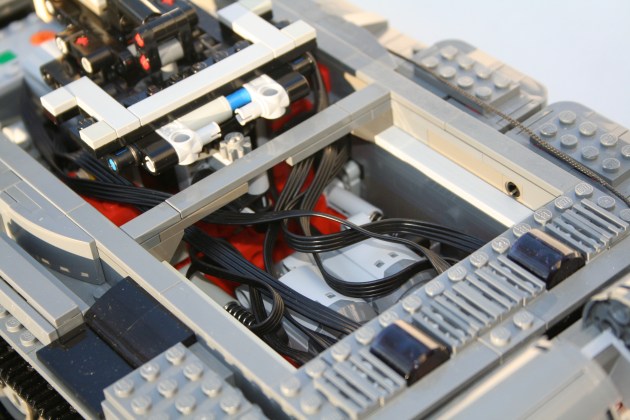
In between each suspension bank are the remaining mechanics. After the suspension was set, I worked on the turret functions. Right from the beginning, I knew the tank would have a rotating turret and an elevating gun. It was clear having the elevation mechanics for the gun in the turret would be tight, so I decided instead to have the functions placed in the hull rather than in the turret. Using a vertically mounted mLA, connected directly to the breach of the gun, I was able to develop a method that would elevate the gun throughout the full turret rotation. The turret rotation was driven by a 8z gear connected to the turntable, and reduced by a worm gear. Both motors for the elevation and rotation are placed directly in front of the turret.
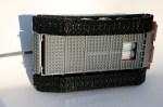
Behind the turret are two PF L motors mounted transversely side by side. They drive a 1:1 gearbox which connect directly to each rear drive sprocket. The IR receivers are placed above the gearbox. For those keeping score at home, the internals are (f to r) the battery box, the turret motors, the turret mechanics, the drive motors, and finally the IR receivers.
Working on the exterior of the MOC is what took the most time. The hull came together pretty quickly, with the exception of the details over each track. Most of the finishing time came with the turret exterior. Most Soviet tanks have the distinctive mushroom turret, which considering LEGO’s cube orientation presented some challenges. The turret of the T-55 also has a slight triangle orientation when viewed from the top. Like the T-72, I designed the turret with four side orientations (left, right, front, and rear), and one top orientation. Starting from the rear, I added a basic curved structure. The sides each had a couple levels of slopes, each tapering in toward the gun. The front was a little more complex. There are two “slope blocks” made of 4 curved slope bricks, and a supporting structure. One slope block is mounted on each side of the gun. The support structure is a mess of bricks with a stud on one side, headlight bricks, and plates. The top of the turret is plates on the front, and two sloped plate sections under each hatch. The two hatches are mounted to the turret support under the sloped plate sections. The AA machine gun is placed on the top, and various external mountings are placed in various ways around the turret.
After making a lot of non-powered MOCs, it was nice to get back into Power Functions. I was pleased that everything worked flawlessly. The drive had adequate traction and power. The suspension worked well, and provided good floatation and travel. The turret rotation was smooth and allowed for precise directions changes. The gun elevation worked great, though I had to limit turret rotations to under four before the clutch on the mLA would snap. After a number of smaller builds, and frustratingly long builds, I was nice to finish something that worked well, provided constant entertainment throughout the build, and turned out quite nice.
I have said it before; I really like set 8081. It has so many possibilities for improvement. After talking a look at RM8‘s design, I thought I should do a street version of the 8081 to follow up on the 4×4 8081 I built a while back.
The full gallery can be found here, and free instructions can be found here.
I took the existing bodywork and frame of the 8081, and chopped out the rear suspension unit to revise the rear suspension design. I wanted an independent setup with a differential. As I have used a couple of times before, I used a floating differential design. The differential is attached to the driveline much like a live-axle set up, but is connected to two independently mounted wheel hubs. I have used this before, and I like the way it works. It allows for a driven axle with independent suspension in a very narrow setup. This way each wheel can move independently, but it does not require two universal joints on each side of the differential. Since the differential is not fixed to the chassis, it has to be braced to the driveshaft. While this set-up is not often used in real cars, it works well for LEGO designs. I used the new wheel hubs, and attached them via a short upper arm, and a long lower arm so the camber would change through the suspension travel.
Moving to the front, I kept the V-8 as in my 4×4 8081, and built the rest of the front around the motor. I used a suspension design similar to 8081, where there are two equal length arms holding the steering pivot. A single shock absorber is used for each side. All told, the car is about two studs lower, due to the new suspension, and the new tires.
It is not much of a redesign, but sometimes I need a project that is not a significant, and allows me to just build something simple.
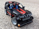
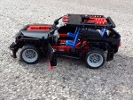
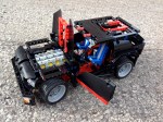
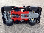
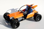
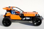
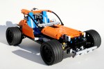
Every once and a while I see something so creative I have to build something like it. I happened with my HH-65. It happened with my Zil 132. And to some extent it happened with my Spitfire. But when I saw the Urban Buggy from Chrismo, I though I have to make something like it. It was such a fresh and creative design. It had such great lines, a perfect stance, and a unique driveline setup. But while imitation and outright plagiarism are the most sincere forms of flattery, I thought something of my own design would be a better contribution to the LEGO community. I present my Talon Track Car.
You may find the full gallery here, and the instructions here.
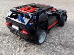
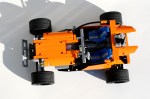
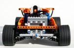
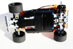
I designed this car to be fast and stable, just like a track car. I started with a drivetrain that would be reliable and effective. A PF XL for drive, and a PF M for the steering. I placed the PF M in the front mounted directly on the suspension unit, with a return to center spring in the middle of the mount. The system is set up differently than in my Rumble Bee, but uses the same return part. Each suspension arm would have a single shock absorber. Directly behind the steering motor was the XL for the drive. It was geared up with a 20z/12z ratio, with the driveshaft connecting directly to the 20z gear that turned the differential. The rear suspension used an independent setup that was developed a long time ago for my Red Car Bigger (great name, huh). If it’s not broke, don’t fix it. The suspension was planted. I placed the rechargeable battery box and the IR receiver behind the rear axle.
The car was quick, and didn’t have any problems, but faster would have been cool. The return to center system worked well, especially for the quickness of the car, and the quickness of the steering. It was easy to control. The car was robust, and crashed well. So go ahead and build your own. Enjoy.
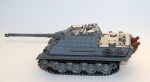
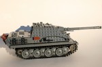
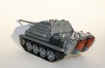
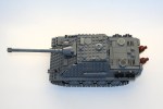
For some of you, this may come as no surprise, but I like to build with more than only Technic. I find a lot of enjoyment building with Technic, but as a child I had more fun with the bricks. My resources (and bricklink.com) now allow me to build some of the things I never could at that time. To this day I still like making tanks, so I present to you a model of the Sd. Kfz. 173 Jagdpanther. This is still one of my favorite tanks: simple lines, great stance, decent performance, and for my purposes, able to be made in LEGO.
While I love building tanks, I don’t build them often. Posting a tank to the LEGO community online is asking for trouble. There are a lot of builders like me who like to build tanks, so it is hard to make a tank that doesn’t take some influence from someone else. While the design is mine, there are a lot of ideas from others that have influenced this design. Feel free to take a look as some of the ideas in this gallery. Thanks to the various builders.
I have some more Technic models in the queue, so until then, enjoy this break from normal.
The full gallery may be viewed here. Thanks for reading.
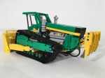
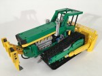
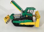
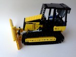
Construction equipment was pretty much designed for LEGO Technic. I learned this while designing my MB Axor Refuse Truck. Yellow bricks are pretty popular and accessible, the equipment usually has many functions which can be replicated, and working models with power functions can be made to reenact various construction projects for great playablility. After finally getting some large track links, I figured it was time for me to do a bulldozer.
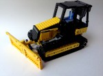
I wanted to model the CAT D5K for a couple of reasons. First, it used a two wheel track for each side rather than a three wheel track for each side. Second, I wanted to do something by CAT. Third, I decided on the D5K because for dozers of this size I think it looked the best due to its stance and overall balance. Plus, when I started looking at the scale of the dozer I was to model, I learned the D5K would work best with the parts needed such as the tracks and blade, and work with the internal space allowed.
The base D5K really only has three functions: drive, blade lift, and blade angle. I had no intention to add a ripper, because, frankly, I ran out of space. Space became an issue very early. I had 9 studs to work with between the tracks, and I needed to add four motors, a dummy motor, a battery box, and two receivers, all while retaining the appropriate look. All the gearing had to be compact, and the linear actuators needed to be placed efficiently. The real D5K has a manual adjustment for the blade pitch, but all of my designs left something more to be desired, so I took it out.
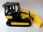
Both tracks would have their own motor, and I wanted to link them to a dummy engine, which required a differential. I connected the motors directly to a worm gear which drove a 8z gear. This gear was on the axle for the rear drive wheel, and connected on the other end to a differential which connected both drive wheels. This differential functioned as a power take off for the dummy motor in the front of the bulldozer.
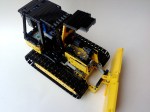
Two more motors were placed under the dummy motor. One connected though a 12z/20z gear reduction for the blade angle. It proved difficult to supply power for the blade angle function through the blade tilt pivot without taking up too much space. The second motor was used to adjust the blade height. After a simple reduction, two mini linear actuators were used to move the blade up and down. It worked well, and was plenty strong.
I added the battery box under the driver’s seat, and placed the two IR receivers in the top of the cab. It was not optimal aesthetically, but it seemed to work well for control. And again, I just ran out of space. I worked on the body, gave the model a working hood, and built a cabin.
The model worked well, but building with tracks is always a little bit frustrating. Like it or not, LEGO plastic will never be fully smooth, and this is compounded with the track system. Also, I found that the dummy motor would lose its connection to the drive wheels, as the axles connecting to the differential would slip out every once and a while. This seems to be a commom problem with Technic builders, so we will see if the new axles will help. I liked the size of this model, and it had a good amount of functions. Now I need to use the tracks for something else.


