T-55A


The T-72 that a made a couple of years ago is still the most popular MOC I have made; at least in terms of internet analytics. This year, I committed to making another tank, so I figured keeping in line with old Soviet armor would be rather apropos.

The main gallery may be found on Brickshelf or at Flickr. Instructions may be found here.

T-55

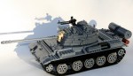
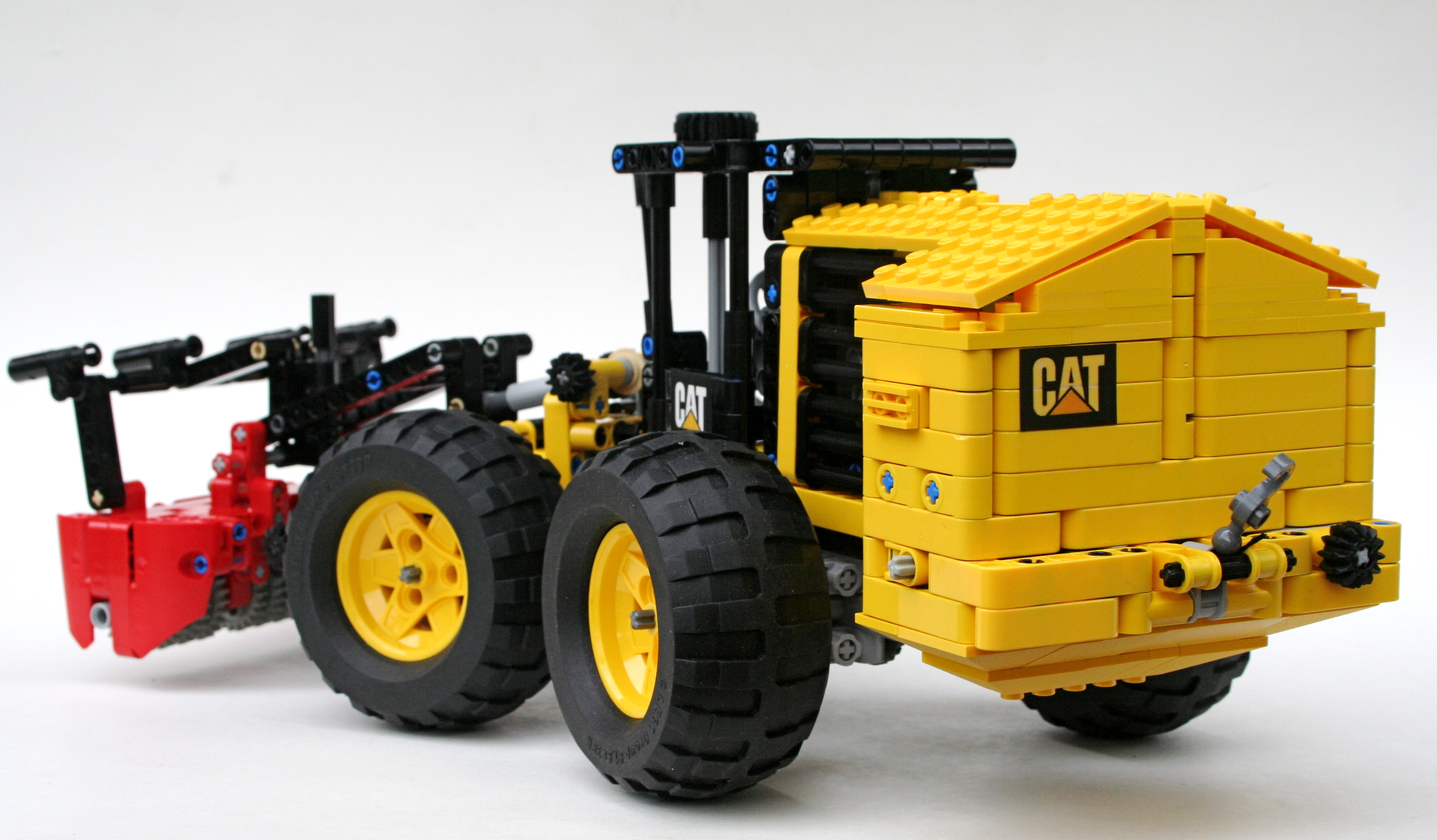
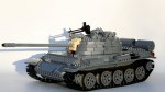
The T-54/T-55 line of tanks have been produced in greater numbers than any other tank. The MOC represented here is a T-55A, representing types that were assembled starting in 1970. This series included an updated NBC and antiradiation system, an upgraded engine, and also added back in the 12.7mm anti-aircraft DShK on the loader’s hatch that was part of the original T-54 spec.

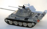
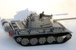
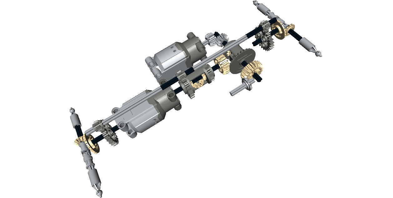
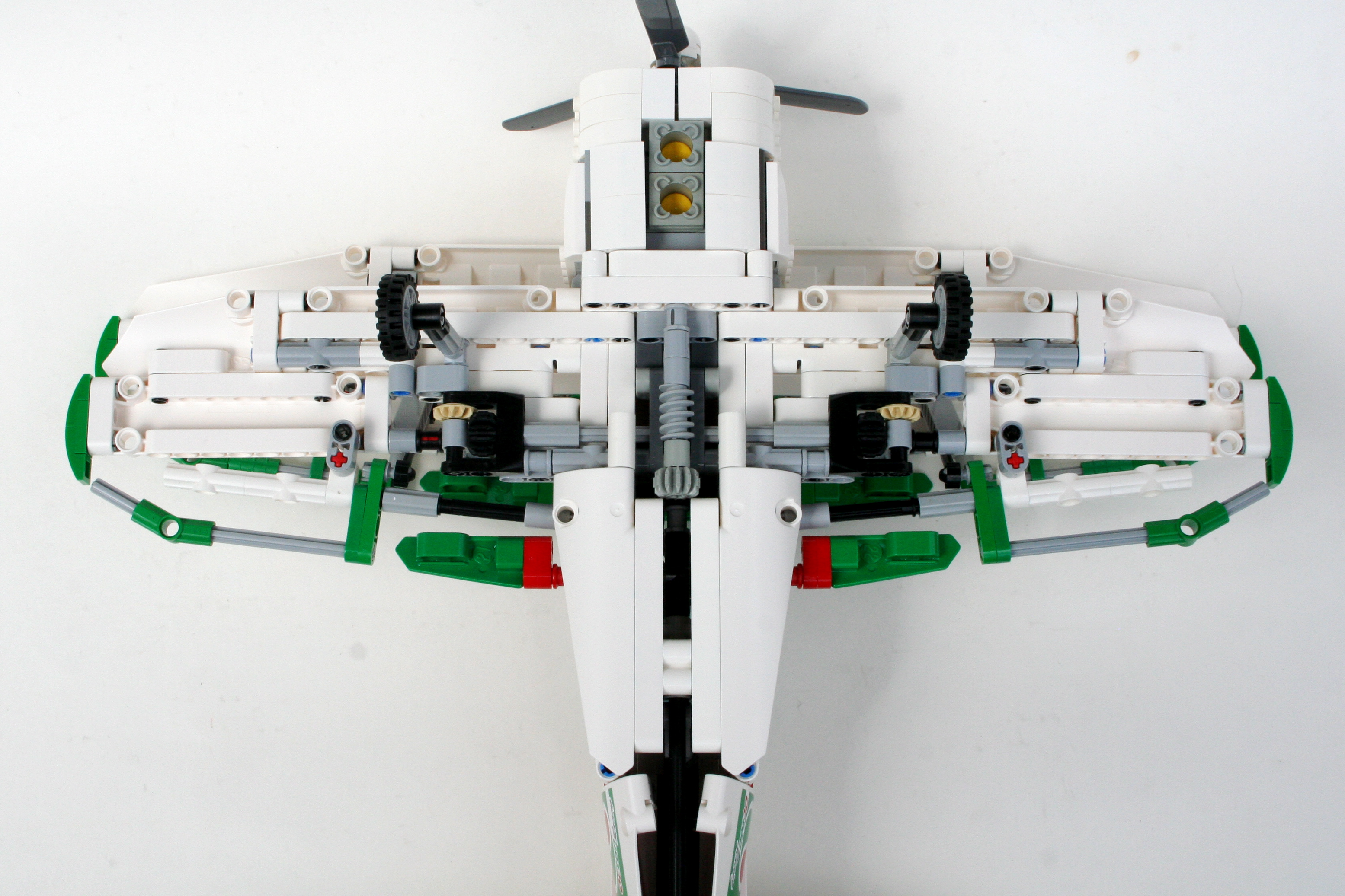
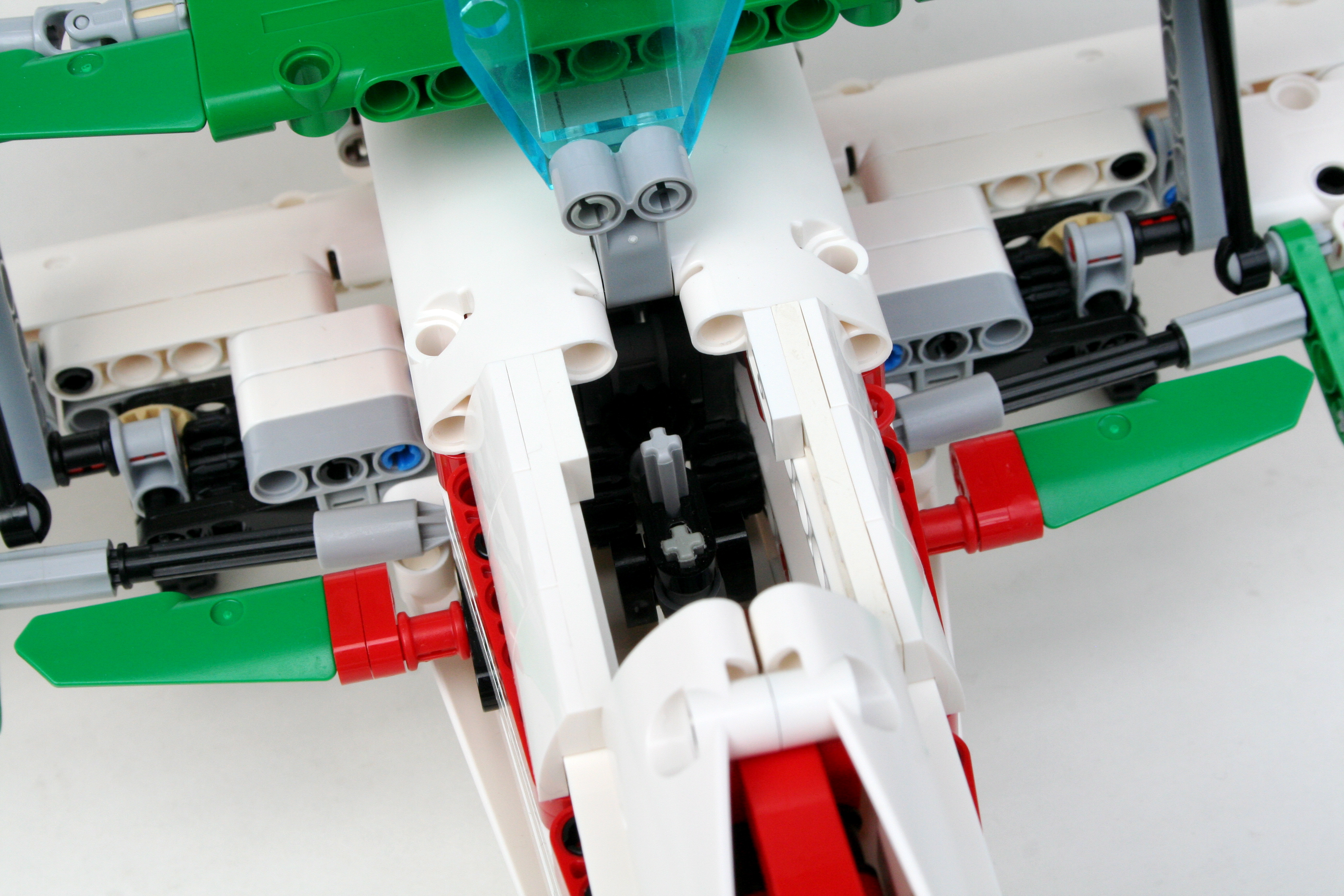
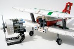
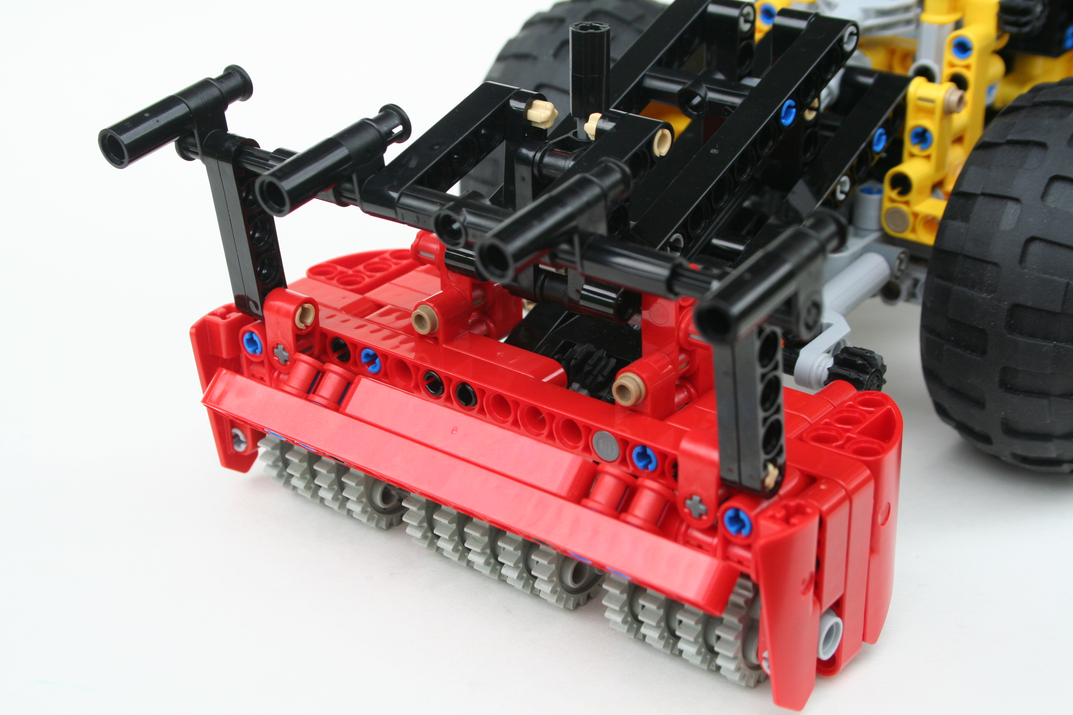
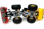
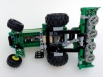
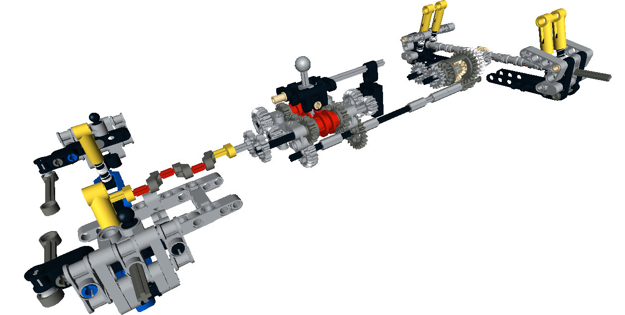
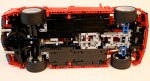
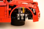
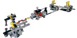
As with most of my MOCs, I starting scaling the tank before any building took place. I knew I wanted to use the newer, larger track links, and I knew I wanted to use the old mid-sized wheels. This set my scale, so I got to work. Starting with the chassis and the hull I worked first on the driveline and suspension. I used simple 2×4 liftarms to connect the road wheels to a suspension axle which activated a shock absorber inside the hull. Each road wheel has its own shock absorber. Fitting them all in took some creativity, but they are all mounted inside on the left and right sides of the hull. In the end, each wheel has about 3 studs of vertical travel.

T-55 Chassis

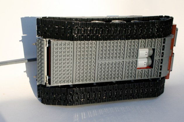
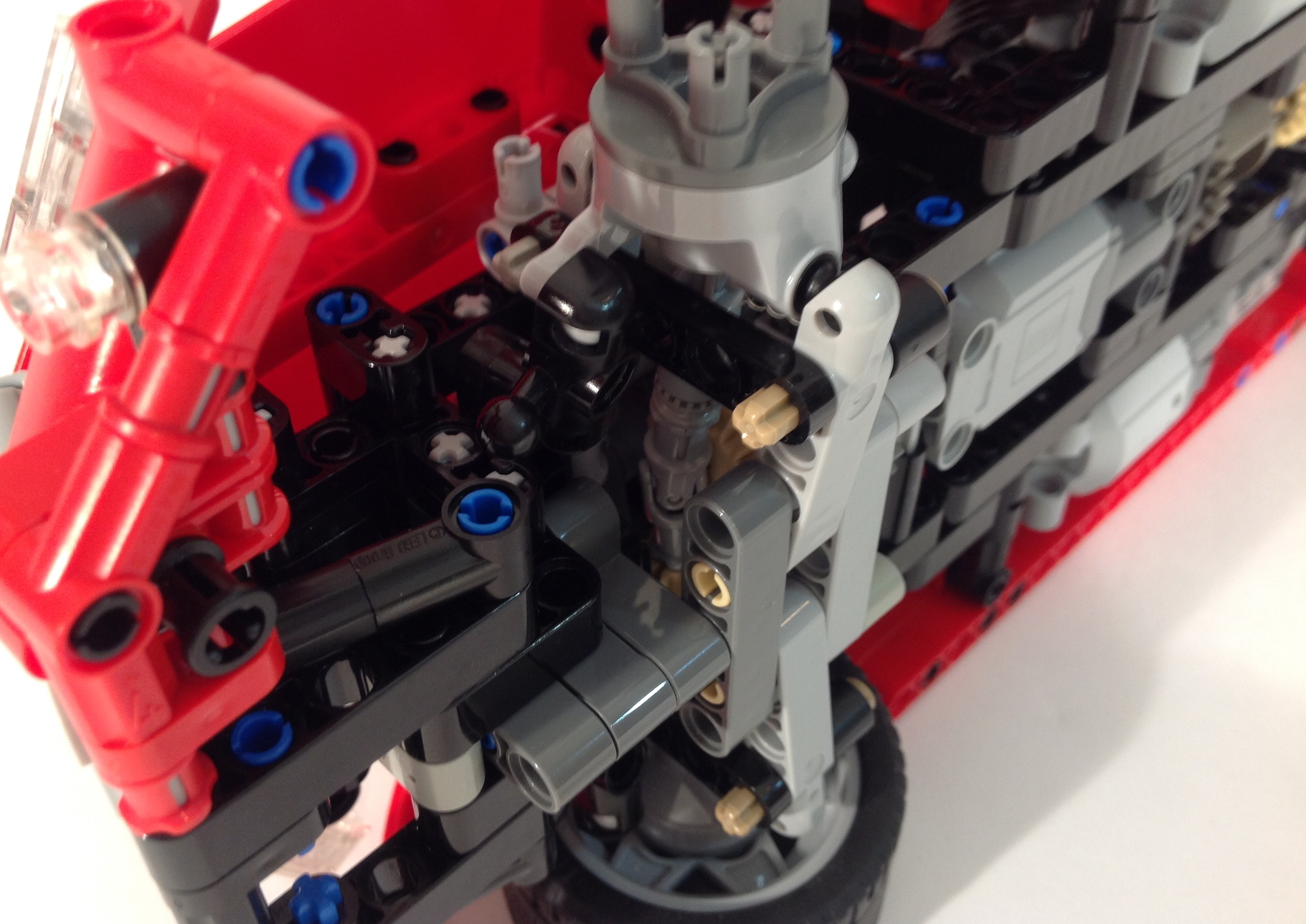
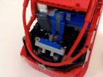
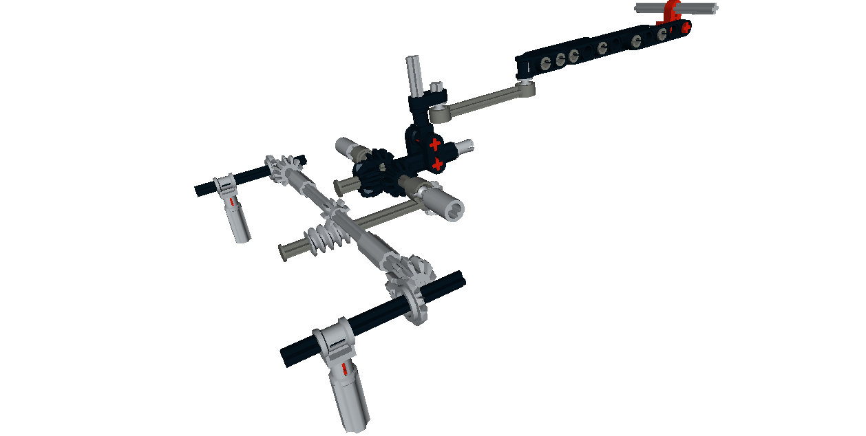
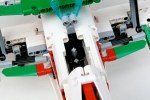
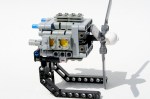
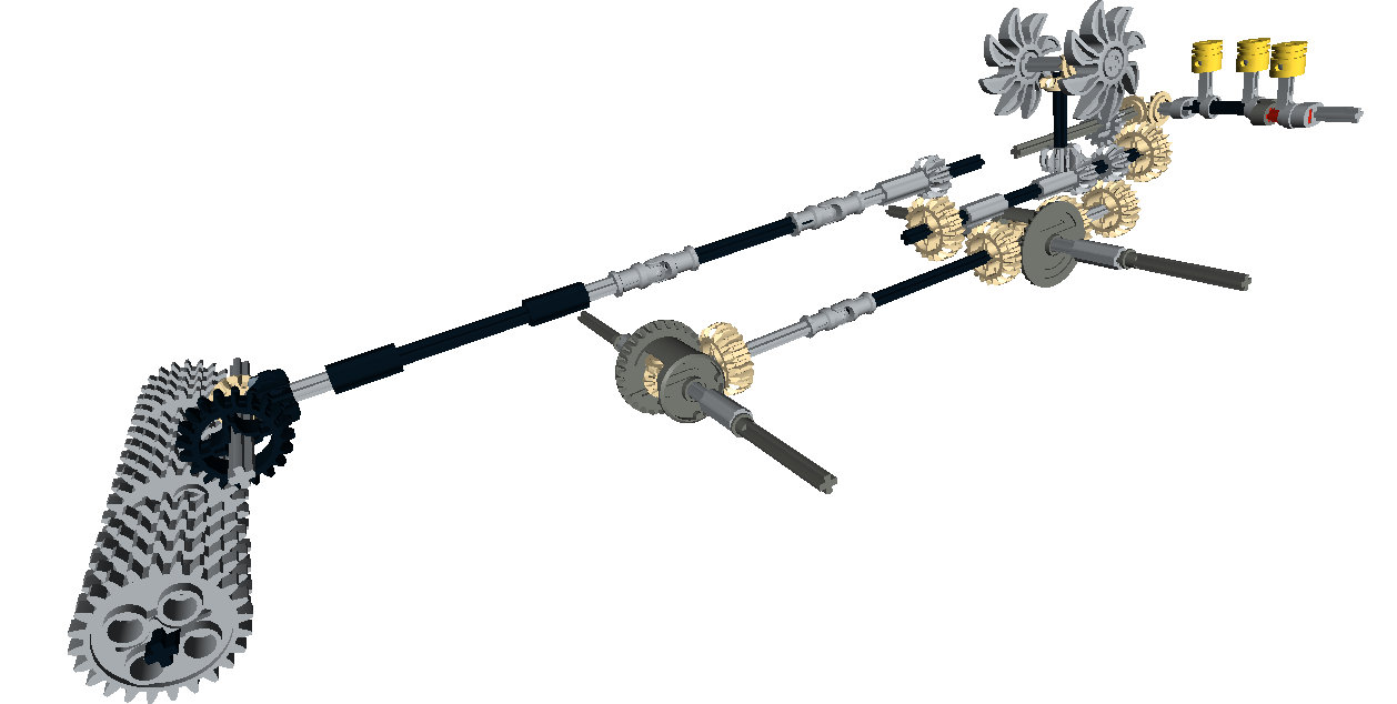
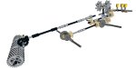
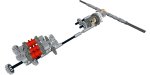
In between each suspension bank are the remaining mechanics.  After the suspension was set, I worked on the turret functions. Right from the beginning, I knew the tank would have a rotating turret and an elevating gun. It was clear having the elevation mechanics for the gun in the turret would be tight, so I decided instead to have the functions placed in the hull rather than in the turret. Using a vertically mounted mLA, connected directly to the breach of the gun, I was able to develop a method that would elevate the gun throughout the full turret rotation. The turret rotation was driven by a 8z gear connected to the turntable, and reduced by a worm gear. Both motors for the elevation and rotation are placed directly in front of the turret.

T-55 Mech
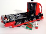
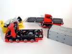
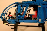
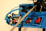
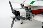
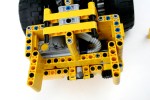
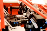
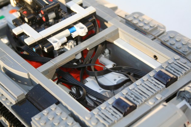
Behind the turret are two PF L motors mounted transversely side by side. They drive a 1:1 gearbox which connect directly to each rear drive sprocket. The IR receivers are placed above the gearbox. For those keeping score at home, the internals are (f to r) the battery box, the turret motors, the turret mechanics, the drive motors, and finally the IR receivers.

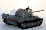
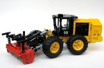
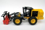
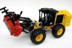
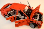
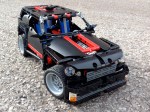
Working on the exterior of the MOC is what took the most time. The hull came together pretty quickly, with the exception of the details over each track. Most of the finishing time came with the turret exterior. Most Soviet tanks have the distinctive mushroom turret, which considering LEGO’s cube orientation presented some challenges. The turret of the T-55 also has a slight triangle orientation when viewed from the top. Like the T-72, I designed the turret with four side orientations (left, right, front, and rear), and one top orientation. Starting from the rear, I added a basic curved structure. The sides each had a couple levels of slopes, each tapering in toward the gun. The front was a little more complex. There are two “slope blocks” made of 4 curved slope bricks, and a supporting structure. One slope block is mounted on each side of the gun. The support structure is a mess of bricks with a stud on one side, headlight bricks, and plates. The top of the turret is plates on the front, and two sloped plate sections under each hatch. The two hatches are mounted to the turret support under the sloped plate sections. The AA machine gun is placed on the top, and various external mountings are placed in various ways around the turret.

T-55 Turret Detail

After making a lot of non-powered MOCs, it was nice to get back into Power Functions. I was pleased that everything worked flawlessly. The drive had adequate traction and power. The suspension worked well, and provided good floatation and travel. The turret rotation was smooth and allowed for precise directions changes. The gun elevation worked great, though I had to limit turret rotations to under four before the clutch on the mLA would snap. After a number of smaller builds, and frustratingly long builds, I was nice to finish something that worked well, provided constant entertainment throughout the build, and turned out quite nice.

Happy building.

Advertisement

Audi allroad


There are not many projects I start that I do not finish. I can count a couple. But, sometimes there are projects that take a long time to complete. I either loose motivation, lack parts (read budget), or find something else to do. If I were wise, I would toss the project, and move on to something better. But there is value to trudging through the slog and completing something difficult. The Spitfire is a great example of this. The Audi Allroad has been on The Queue for about 16 months, and it’s finally done.

The full gallery may be seen on Brickshelf or on Flickr.

Audi allroad

After completing the OCTAN F1, I thought I could use the suspension for an all-wheel drive car. I was sure I could make the front suspension with steering work at this scale.

allroad Suspension

I wanted it to have another fun feature, so using a bunch of differentials, I developed a simple three speed transmission. Three power functions motors are connected via two differentials which connect to the drive axles. Each differential acts as a subtractor between each motor. When one motor is running, the power moves through two differentials, and the car moves slowly. When two motors are running, the power moves through one differential, and it’s a little faster, and when all three motors are running the car is running the fastest as no differentials are splitting the power. I got it to work, and within a day, I had a working chassis.

allroad Driveline

Once this was done, the MOC sat on my desk for a long time. This past fall, Thirdwiggville welcomed another citizen to the village, and this gave me lots of time late at night to get back to working on this project. I spent a couple of weeks working on the body work with the perspective of “finish this.” So the body work could use a little more polishing; doors, mirrors, better lines, maybe an interior. But I was happy to finally get this done.

The MOC worked well. The suspension functions quite well at this scale, and the transmission was simple and effective. It could be a little quicker, but I was not going to make a substantial gearing change after the MOC was built.

Two final thoughts. I need to stop building supercars because they take a lot of time and effort for me, and I find little motivation for the body work; I do not think the body work looks good, and I lack motivation to work on it. Second, I needed to test the driveline earlier in the build process. I spend too much time fiddling with gear ratios after everything was build. But this project is done, and I am happy it is.

Happy building.

2045 Mercedes-Benz Athane


I enjoy participating in LEGO contests, but I cannot join all of them. Sometimes the timing, my build interest, and the available parts all line up in a way that I can submit an entry. I was able to submit something for the LEGO Technic Mercedes-Benz Future Truck Competition hosted at Rebrick.com because everything fell into place. I hope you enjoy the submission.

The full gallery may be seen here (flickr) or here (brickshelf).

Mercedes Benz Athane

While I would love to see us progress to flying and fully autonomous vehicles, a complete technological and transportational paradigm shift needs more than 30 years; see where we were in 1985. I envision transportation in 2045 will be affected by a couple of features:

  • Cities will be more dense
  • Active transportation will occupy a greater share of road users
  • Electric charging options will be more available and more diverse
  • Vehicles will still have drivers, but the drivers will be heavily assisted with technology
  • Fossil fuels will still be used, but significantly reduced and not limited solely to petroleum
  • Cargo will not change, but storage will
Various loads to apply to the Athane via the SmartStack System.

Various loads to apply to the Athane via the SmartStack System.


With this is mind the 2045 Mercedes-Benz Athane has been designed to best fit within this context. While taking this context into account, the Athane prioritizes three values as most important: Safety, Sustainability, and Versatility.

Placement of the large methane tanks. ThermoCommLink on right rear bumper.

Placement of the large methane tanks. ThermoCommLink on right rear bumper.

Here is the Press Release-

May 22, 2045, for immediate release

The 2045 Mercedes Benz Athane prioritizes safety, sustainability, and versatility. The 2045 Athane is the most advanced and cost effective truck in our 150 years of truck building experience.

As cities become denser and multiple transportation modes are becoming more prevalent, road safety for all road users must be paramount. The Athane’s ThemoCommLink (TCL), located on the right front and right rear bumpers, allow motorized vehicles to communicate to one another. The TCL also detects the heat signature of pedestrians and cyclists. Identification and communication with other users, keeps all road users safer. The driver is seated in the center and forward in the cab to increase vision. Retention of a human driver allows for relational interaction at the job site, and helps the technology make good decisions about varying road situations. The TCL Technology assists the driver so fewer errors are made. The front bumper shaping and full length wheel guards lowers the severity of crashes with non-motorized users should they occur. The Athane uses eight steerable wheels to improve weight distribution and increase city maneuverability. While many manufactures are switching to floatation and hover type drivetrains, this setup allows for unmatched braking control, and removes disruptive air currents to those walking and cycling close to the moving truck.

The Athane’s Methane-Hybrid driveline continues Mercedes Benz’s prioritization of decreasing fossil fuel use. The Athane uses electric propulsion using energy stored in the batteries under the cab and bed. Battery charging is done by braking and by a small methane powered combustion engine behind the cab. Additionally, the Athane can be ordered with an induction charger under the cab to work with newly developed induction charging roadways being installed in many municipalities. Methane gas is clean burning, and a significant byproduct of the waste and recycling process currently in place with Octan Rubbish. A partnership with Octan Energy and Mercedes Benz has developed a standard way to reap, store, transport, and fuel the Athane’s regeneration engine using methane gas. Removable methane tanks are house behind the rear wheels, and in smaller tanks in the cab.

Today’s logistics companies are searching for ways to improve versatility and lower cost. The Athane’s SmartStack systems allows for interchangeable bodies, cargos, and applications all with one common truck. The SmartStack system makes it easy to change the load in just minutes. The connection fits the international container standard. Many body work designers are applying this standard as well. In one afternoon, you can ship a container, deliver a load of concrete, and pull a fifth-wheel with the standard hitch.

Welcome to the future. The 2045 Mercedes Benz Athane keeps all road users safer, decreases our harm on the planet, and supports all work tasks needed.

Features:

  • 8 wheel steering
  • Sleeping bed
  • Aerodynamic cabin
  • In-cab Storage System
  • ThemoCommLink, front and rear
  • SmartStack System
  • Fifth-Wheel Hitch
  • Wheel Guards
  • Large/Low Bumper
  • Methane Tanks
  • Hybrid Motor
  • Induction Charger
  • Batteries
  • Passenger Jump Seat
  • Front and Rear Lighting
  • Video Mirrors on Each Side of the Steering Wheel
  • Visibility Focused Driver Placement

MD600N


One of my first memories of a helicopter was watching a Phoenix Police MD520 land in Roadrunner Park, a block away from my house. The high pitch whine of the main prop was incredible, but another sound was missing. I gathered all my seven year old courage, and asked the pilot, “where is the tail rotor.” I got a lesson in aerodynamics that day, and to this day I can still identify an MD520 by sound. It still remains my favorite helicopter, so I figured it was high time for me to honor this aircraft in LEGO.

Full gallery can be found here. Instructions may be found here.

MD600N Front

What excites me about building with LEGO Technic is creating functions that allow motor, movement, and control. Helicopters are mechanically complex, so I find myself drawn to recreating them. I learned about how they work when I built my first helicopter. With this new helicopter I started with the rotor head. I first built Effermans great swashplate design, and figured out what should stay and go. A four blade rotor head seemed not quite right, so after a little work, I managed to get a six blade head. It was with this decision, and discovering in the chosen scale there would be very little internal room, that I decided to switch to making an MD 600N.

MD600N Starboard

I then got to work setting dimensions, and getting the scale of the airframe correct. The length of the rotor blades dictated the scale, and the interior was going to be tight. The major challenge was getting the control functions connect to the cockpit. This is not a new challenge, as it seems to be the case with every large plane I do. I have a lot of experience with it, and so I came up with some solutions. The challenge with a helicopter is the collective. Every movement that is transmitted, must be able to retail its movement while also being effected by the collective. This works well with the swashplate, but at the controls is where this gets difficult. Using the basis of Effermans design allowed for a simple setup where the collective moves an axle on which the the left/right and fore/aft controls mount.

MD600N Cockpit

_MG_2539

Moving the collective moves the other two controls in a way that is independent from joystick inputs, and allows for complete swashplace articulation at any collective pitch. The controls connect to the swashplate above the main cabin and move forward. From there all three fuctions move down to the floor of the cockpit in between the pilot/copilot seats, and the second row seats. The collective is connected here to a lever on only the pilot’s side. The left/right controls connect via an axle to the joystick, and the fore/aft controls connect via a 9L link to the joystick. Both joysticks are linked together.


MD600N Chassis

The final control adjusts the yaw of the aircraft. The MD600N uses three methods to give anti-torque to the main rotor. In forward flight the 1)  tail planes give directional stability. The tailboom also has 2) two slits that provide a “Coanda Effect” from the main rotor downwash. Finally, at the end of the boom is a 3) movable jet direct thruster (all are nicely discussed here). This thruster rotates to force more or less thrust against the torque of the main rotor, much like the more common tail rotor. In this MOC, the thurster rotates on a small turntable, and has an axle running through the boom the controls the rotation. The axle connects to the floor petals by way of a flex cable, and a liftarm running below the cockpit. Both pedals are linked together.

Once all the controls were set, I could work on the body. I wanted the helicopter to be blue as I see it in my memory (almost). This presented some parts challenges, but not as many as I expected. The two suicide doors open to the main cabin, though I did not add any to the cockpit. Many liftarms and connectors were used for the rest of the cabin. I wish current Technic parts could facilitate the rather bubbly lines of the MD600N, but I was pleased with how it looked in the end.

As with many of my large aircraft, this helicopter suffered from gummy controls. The range of motion of the controls reflect the scale for the model, but do not allow for great playability or demonstration of features. For something like a helicopter, I am interested in powering the controls surfaces and inputs controls via Power Functions much like this. Next time I guess. But the Helicopter looks great on my shelf, and it brings me back to a great time in my childhood. I hope you enjoy.

Happy building.


OCTAN Air Racer


OCTAN is one of my favorite longitudinal themes of LEGO. It gives a little color and identity to many of the racing vehicles that have been produced by LEGO since 1994. I don’t know why it took me so long to start making MOCs with an OCTAN theme, but after last summer’s OCTAN F1, I figured I should do another one.

The full gallery including instructions may be seen here.

OCTAN Air Racer

It was time for me to build another airplane, and I figured a0 small air racer would work well in the OCTAN colors. Right from the beginning, I was sure I wanted to make a biplane, and I wanted a radial engine (all real airplanes have propellers). From there everything was on the table. Off to designing.

I started with the radial. It’s not quite a radial, but rather two perpendicular boxer 4 cylinder engines. Each bank of two cylinders are mounted in a different direction; up, down, port, and starboard, and are connect by one common crankshaft. The side banks are one stud forward, and the up and down banks rear, so all eight connecting rods can fit on a common 5l axle. Two engine crankshafts are mounted at each end. The motor spins well, and quite quickly, but the connection is not exactly “legal,” as the pins on the cylinders are a little stressed.

8 Cylinder Radial

Working backwards, I attached the leading edges of the wings, and the worked on the landing gear. Being an air racer (even a biplane), it had to have retractable landing gear. I connected the two wide spaced legs with a simple axle and bevel joint, and added a worm gear to articulate the action. It is a simply solution, and it functions well.

Air Racer Bottom

Just behind and above the worm gear is the joystick. The roll functions are connected to the bottom wing by gears, and the pitch function is connected by liftarms to the rear elevator. The rudder is fixed. The lower ailerons are connected to the upper ailerons by a simple 9L link. When you move the joystick, all four ailerons move. The cockpit is a little cramped, but when you are racing space is not a concern, only speed.

Air Racer Drive


Air Racer Cockpit

After the radial, the bodywork was the priority for the MOC. I have been slowly acquiring white and green parts over the last year. The airplane was designed as primarily white, with red and green accents. The red stripe worked well, as did the red tail, but I could not find a great way to incorporate the green. I added a little to the tips of the wings, and to the wing control surfaces. I used a couple more stickers that I had left over from set 60025, and the MOC was finished.

I was pleased with how the MOC turned out. The airplane looks strong, and the red and green make the white vibrant. I wish I could have found a better place to incorporate the green. The places it was added seems a little haphazard. The radial turned out great, but I feel a little bad about the illegal build. The landing gear works well, as do the control surfaces. I was pleased with how it turned out. Next up, maybe an OCTAN speedboat. Other ideas?

Happy building.


CAT 586C


My favorite constructions vehicles are feller bunchers. The wheeled ones. So I am naturally inclined to make them. I built a small one; I built a large one. I wanted to build a medium one, but I figured I should get out of the box. At least this time.

The full gallery may be seen here, and instructions may be found here.

CAT 586C

The CAT 586C is a site prep tractor. Forgive me for simplifying the work done by the engineers, but the tractor is basically a 573C with a new implement for site preparation, rather than felling. As always, I stared with scaling the full tractor from CAT’s website, and finding a size that would work well with tires, features, and aesthetics. Then I started building.

CAT 586C Rear

I started with the chassis, to get a sense of the size and the layout. I had a good idea of all the features I would want, and I knew some planning would be required. I then finished the mulcher (implement), which is basically a rotating drum with lots of teeth on it. I used a bunch of 24 tooth gears, and connected them to a rotating driveshaft. The chassis was built with four wheel drive, and was connected to the mulcher driveshaft through a series of gears to increase the speed of the drum.

CAT 586C Underside

Then on to the back of the tractor. Feller bunchers and site prep tractors all have their engines in the back; pretty normal for large tractors with large front implements. But to get the weight as far back as possible, the engine is mounted transversely. This presented a couple of challenges for me. I mounted a I-3 engine on the left in the rear with simple gearbox geared up to connect it to the drivetrain. Just in front of the motor are the two cooling fans, which are also driven by the drivetrain. These are also geared up. For those of you keeping score at home, the drivetrain gears up three separate functions, so rolling the MOC on the floor causes a nice whizzing sound.

CAT 586C Driveline

I added some additional features that mirror the real tractor. First, over the mulcher there is a guide bar that allows the tractor to push trees and shrubs down toward the mulcher. In my MOC this is accomplished by a simple worm gear mechanism. Second, I added a small winch on the rear to get the tractor out of sticky situations. Finally, a small mulching door was installed to allow for more or less entry to the mulcher, again just like the real tractor.

CAT 586C Mulcher

The tractor worked well. Functions were smooth, and required no maintenance during play. The many controls on the front were a little dense, and this caused some finger congestion. The number of rotational features connected to the drivetrain made rolling on the floor a little strained. Thought, this kept the MOC from rolling off the table into a lot of pieces. Everything worked well enough, so maybe it is time to make another feller in this scale. Not today, I still have a lot of other projects to complete first.

Happy Building.

Thirdwiggville


About a year ago, Mr., Mrs., and Jr. Thirdwigg packed up some boxes and left Chicago for Grand Rapids. Along with many other changes, this relocation provided myself a room devoted to LEGO; well at least until it will be commandeered (shared?) as a family play room.

LEGO Room

It is not too fancy, but it works well. The room is in the attic of the house without heating or cooling; the summers get a little hot, but the winters are fine. I have two little tables on which I do my building, and four organizing shelves that keep many of the high use parts close at hand. Tires, books, and empty bricklink packages are strewn about, at least until I can muster up the gumption to put them away.

LEGO Table

Organization is always a work in progress, and as you can see, some things need to be put away. Careful eyes can see some projects from The Queue that are getting close to completion.

LEGO Shelf

The room has some nice build in shelves on both sides of the room. As you can see, I keep a lot of infrequently used parts in bags off to the sides, and some of the larger Wheels and Tires. I also keep an large box on the floor for when small children want to come over and play in Uncle Thirdwigg’s LEGO room.

Happy building. More MOCs will be finished soon.

Windrower


At any given time I have about 4-6 projects going on at a time. This is partly the result of the Queue, which is partly the result of my lack of focus. In the midst of all this planning, I find it therapeutic to sit down, and start something small, simple, and without a plan. Two weeks ago, right after finishing the ATS, I sat down, and in a couple of hours, completed a small windrower.

The full gallery including instructions may be found here.

Windrower

Some of my favorite MOCs are the smaller non-motorized ones I have done over the years, like my Feller, my Octan F1, my 4×4 8081, and my Sod Harvester. I built the Windrower to fit in this theme. A Windrower, or Swather, is basically a large lawnmower. The blades on the front cut down hay, and pull all the cuttings to the center to make a row of cuttings, or windrow, to be picked up later.

My version is rather simple. The two main wheels are connected to a center differental through two 8z portal axles. The differential drives a small I3 motor in the rear, and a PTO driveshaft comes out the front. The PTO drives a simple harvesting head made of four z24 gears which are connected with a number of z12 gears. The harvesting head can be raised and lowered by a simple worm gear setup. A simple steering system was created for the rear wheels, and it was connected by a liftarm to the smoke stack so you could control the steering.

The body work took a couple of Bricklink.com orders. After recently making a couple of MOCs in red, I felt the Case IH coloring would be a little redundant, so John Deere Green it was. My collection of green is growing, but there were still some parts needed. After everything arrived, I replaced all the red, and added some yellow wheels, and everything was set. A simple MOC, with some fun features, and an infrequent color.

Happy Building.


Cadillac ATS


A while ago I decided I was going to do a proper new school supercar. Something with all the features that are to be expected in the LEGO Technic Community. You know what they are; suspension, a gearbox, opening doors, a working engine, steering, and something fast looking. Probably red. It was time to test my chops and throw my hat into the ring.

The full gallery can be viewed here, and instructions may be purchased for $9 USD. Partlist

Buy Now Button

Cadillac ATS

It has been a long time since I have built a supercar. While I enjoy many of the cars others make, I long for exceptional creativity in suspension design, gearboxes, and body style. It was time for me to build another one and contribute to these areas. About two years ago I set out to create a six speed gearbox that would have a more realistic gear change movement. I tried linkages, springs, and so many gears. In a bit of a breakthrough, I offset the two outside changeovers vertically by 1/2 stud. This allowed for the changeover lever to connect all three changeovers as it rotated from a single center pivot point. Once this design was completed, it needed a home.

ATS Transmissions

I have a preference for sedans rather than coupes. Plus too many two-door supercars have been created. Forgive the slight nationalism, but I thought it would be fun to do an American sports sedan, so a Cadillac was the best choice since the demise of my beloved Lincoln LS. The ATS was new, and at the scale would be a little more manageable than the CTS. I worked a little on the scale of the car. Some parts would be a challenge to convey the look, but I was ready to start building.

I started with the front suspension. The new suspension arms allowed for a short/long arm setup. The two different arm designs allowed for a increasing negative camber as the suspension moved through its travel. Additionally, the pivot points on the steering hub allowed for a kingpin inclination to provide an improved caster angle. Finally, I added Ackerman geometry to the steering link. After some work mounting the suspension, and the rack and pinon steering, I had the front suspension done.

ATS Front Sus

The rear suspension was more simple, but still had some unique features. While the real ATS uses a 5 link setup in the rear, I was not too impressed with the results I came up with as too much flex was found at the wheel. I started with a transversely mounted limited slip differential that I have used before. This connected directly to the two half-shafts for the rear wheels. I applied a short/long arm setup for the rear suspension so the tires would keep their contact patch as the body would roll through a corner. Like the front, this created increasing negative camber as the suspension moved through its travel. Normal in real cars, not often replicated in LEGO.

ATS Chassis

Tying all of these parts together was a little bit of a challenge. I wanted the steering wheel to be connected to the steering as well as a HOG knob on the dashboard. In addition, the doors, trunk, and hood should all open. Naturally, the car had to have a spare tire, and various engine options which could be easily removed. The chassis had to be stiff enough for the suspension to function well. Packing this all together took some time. About 9 months, but who is counting?

ATS Left Front

But what took the most time was the body work. This is the part for which I have little motivation, and the important part that would identify the car as an ATS. I had a lot of work to do. And my palmares have not trained me well for this task. After major parts were placed, and the dimension were set (37 stud Wheelbase, 60 stud Length, 25 stud Width), I worked on one section at a time. As the front bumper was part of the chassis, this part was developed early. As did the rear bumper. The headlights are unique for the ATS, so this was done early as well. After the roof was placed I worked on the trunk, which came together rather easily. I worked on the hood of the car, and after two designs I was happy with the result. I then worked on the grill, and after tinkering with a couple of SNOT techniques, I was able to get most of the distinctive Cadillac grill in my design.

Cadillac Grillz

Then off to the doors. I made seven designs. Most sedans these days have various creases that identify their sedan as different than any other sedan. You will notice the ATS has two, one on the bottom that rises slowly to the rear, and one midway up to the windows that moves along the length of the car from the hood to the trunk. The top line was accomplished by having the angle for the windows start a little lower on the front door and higher by a 1/2 stud on the rear door. The bottom crease was added by attaching some angled plates to the bottom of both doors, which cant slightly inward. Finally, both doors have an upper pivot point that is 1/2 stud inboard to bring the upper part of the doors toward the center of the car. Once I got a design I liked, I had to bring it all together to make sure everything fit well. I adjusted the roof, modified the hood, tightened up the dashboard connection to the doors, and made some changes to the rear quarter panels. There were still some areas where improvement could be made, but I was running out of ideas. I was pleased with the result. Pleased enough to say I was done.

All in all, I was pleased with the result of the car. As this is my first studless supercar, I was happy with how it turned out. The functions were up to my standards, and nothing was compromised as the car came together. While I was overwhelmed with the bodywork, I was pleased with how it turned out. Because it took me a long time to get it to work, it may be a long time before I do another one. I was happy I did a sedan, and hopefully a new moniker can begin in the LEGO community. #supersedan.

Happy Building.

2014


Another year comes to a close here at Thirdwigg.com. A lot happened this year. Let’s recap. 2014 started with Thirdwigg Jr., it continued with Brickworld, and the addition of some projects that were not part of The Queue. I moved (without the loss of any LEGO elements I might add). It also included one of my MOCs being published in a book. It was a year that was a little more prolific than I had originally planned, while some of the MOCs I planned were not completed. As a recap, I completed the 8081 RT, Iveco XTR, JCB 714, Business Card Holder, Hawker Typhoon Ib, Silly Fat Penguin, JCB 531, Octan F1, Kenworth T47, and Updated 8386.

Here are some reflections. I built my first animal and it was a fun project. The Octan F1 turned out much better than I would have expected. The Typhoon was much better than the Spitfire, and it worked very well. I very much enjoy the small projects, but I learned this last year. I find these projects challenging for the driveline, and for the space constrictions. Also I find the bodywork frustrating as MOCs get larger. This may be part of my adversion to supercars.

My photography and productions skills need to improve. This will take some time, but hopefully I can learn some new skills to make this better. It is good to remember what I haver learned and accomplished in the last ten years. That time has flown by.

The Queue has been a fun addition to this blog. It keeps me motivated, and allow me a space to document ideas. OK, I also have a Google spreadsheet, but that’s a little like a mind dump, so I do not need that here. Plus I can add additional pictures there, and that’s always fun.

For 2015, here are some new goals. Last year, there were some large projects that were planned, and some were smaller and developed organically. While it is good to set some goals, allowing for some space for other ideas to work in is a good idea.

I started the Cadillac ATS 11 months ago. It needs to be done.

Finish the MD600. It’s close.

Create a small scale all-wheel drive car.

Design another working forklift.

Build another tank.

Make a midicar and make it power function driven.

Create a complicated trial truck.

Complete another garbage truck. I’m looking forward to this. I love garbage trucks.

Again, two small projects with about 500 pieces. Most likely manual functions, and one will be yellow. We’ll see what pops into my mind. I take suggestions.

Here’s to 2015. Happy building.