Concept John Deere Bulldozer


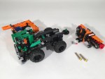
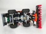
In what is becoming a little bit of a theme, I submitted another design for a Lego contest. In the long line of Eurobricks.com contests, the Technic Challenge 10 called for a pneumatic build. Challenge accepted!

Full Gallery Here

Concept John Deere Bulldozer Left

The contest had very few constraints other than the build had to use Pneumatics. As I have mentioned before, working with pneumatics is not my preference. I don’t like them, so it was good for me to step out of my comfort zone.

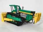
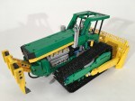
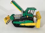
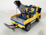
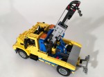
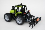
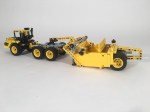
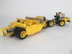
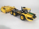
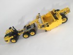
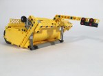
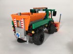
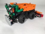
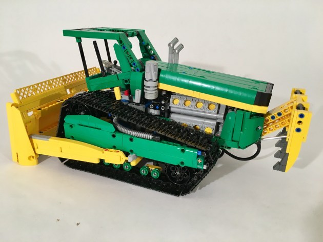
I was feeling especially creative this time, so I thought about a number of concept ideas. Pneumatics do not tend to work smoothly when lifting arms so I decided against an excavator and a loader early. Additionally, I was not willing to invest in additional parts for this project. After a couple of drafts, the idea of this bulldozer was born. Taking some inspiration from some of John Pope’s design, the basic idea was there. The dozer would have different tracks, a three movement blade, a crazy engine, and a forward thinking design.

Concept John Deere Bulldozer Blade

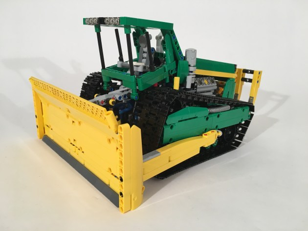
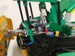
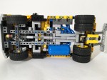
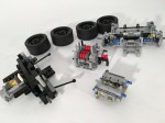
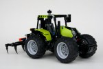
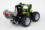
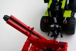
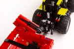
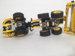
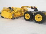
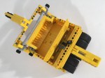
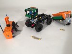
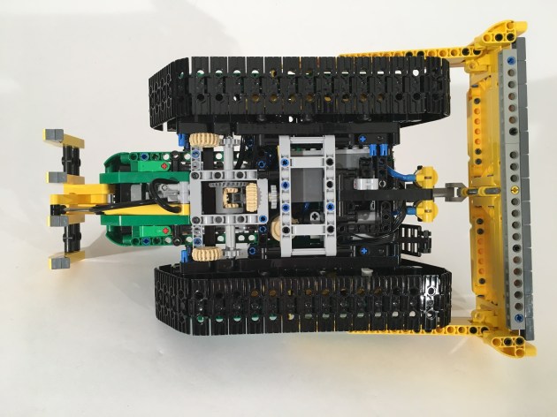
I started with the tracks. After moving the axle points four wheels countless times, I came up with a design I liked. I made another one, and linked them together. The I worked on the blade. The dozer would have a lift, tilt, and side to side angle adjustment. After playing around with some idea, I found a solution I liked. Two pneumatic rams were on the front to lift the blade on the top. Then two links were connected low on the two sides of the blade, and then on each side of the dozer. These points on the dozer were moved fore and aft by on pneumatic ram each. These side rams would move the blade left or right individually, or together they would tilt the blade up or down. Additionally, it allowed all the tubing to be internal.

Concept John Deere Bulldozer Open

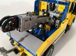
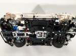
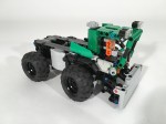
I added a small compressor powered by a Power Functions M motor, and the battery box under the cab, and added the 16 cylinder engine (coupled V-8 and Flat 8). The cab was easy to get the shape I wanted, and gave me some space for another pneumatic ram to open the hood. I then decided to add a ripper since I had one pnuematic left. The new 1×11 ram a great addition, but a little more power could have been used for the ripper.

Concept John Deere Bulldozer Chassis

I was pleased with the look the bulldozer. The functions worked well, but on reflection, the were not exciting enough to be competitive for a contest. After two pneumatic builds in a row, I find some of the frustrations I have with them remain, but I am discovering some charms as well. We’ll see what comes next.

Happy building.

Advertisement

International Tow Truck


I have so many pneumatic parts, but I do not build with them often. It was time for me to use them.

DuraStar

Since this would be an intentional pneumatic MOC, I wanted to do something small and simple. I thought a tow truck would work well. As many of my trucks are based on Europian models, I figured it was time to do an American truck. The International DuraStar truck seemed to be a good solution, and they are rather ubiquitous her in the States. It is not too big, and not a pick-up based truck, so it was perfect for me.

I first started with the tow boom. I used the new 1×11 cylinder for the boom extension. I used two of the old 2×9 cylinders for the boom lift. I worked hard to get the boom rigid enough for the extension while remaining small. Still the boom is about twice the width and height of the required scale. It is a little flimsy with a heavy load.

DuraStar Hook

The chassis was more work than it should have been. Working in all the pneumatic parts is simple enough, but giving space for all the tubing and flexibility required much work. Add to the fact that the  chassis needed to be strong enough for a Pneumatic pump, and I thought it would be good to have a working driveline, and it got messy fast. Editorial comment: I like clean designs. It’s hard to have clean designs with pneumatics.

DuraStar Chassis

The rear wheels connect to a 2 cylinder fake motor in the front. I did not use a differential. It fits, but I could not find a solution to keep the wheel axles connected to the differential while retaining the rear dualies. All of a sudden the choice of not having a differential in 42022 makes a little more sense. I added a little car lift on the back. The elevation is controlled by worm gear, and the extension simply uses two friction connectors. In front of the dualies is a pneumatic air tank on the right, and the two control valves on the left. Hoses fill up the rest of the space. Above the air tank is worm gear transmission for the winch.

DuraStar Right

I spent a lot of time working on the hood. The cab came together smoothly, but the hood took some work. Working with something that was rigid enough for my standards took some time. I tried some designs with panel, and some designs with plates and wedge plates. Eventually, I settled on a simple studs-on-top brick and plate construction. The mixture of Technic and system looks a little disjointed, but it represented the shape well.

The truck worked well enough. The steering and fake motor worked smoothly and consistently. The pneumatics worked smoothly, and were able to move the functions of the truck well. The car lift on the back cannot handle too much weight.

Two final editorial comments. I am firmly in the linear actuators camp, as I have said before. Fitting rams, running tubing, and trying to use those little valves just to get position of the pneumatics perfect drives me crazy. Second, I really like the 49.5×20 wheel and tire set. It is a great size and has perfect look. But when I build trucks with them I get frustrated. They look better as dualies on the rear, but there is no good connection to a differential on a 15 or 17 wide setup. Eventually I will find a solution, but at this time, they are driving me crazy, so stay tuned.

Happy Building.

Volvo FE Garbage Truck


My favorite vehicles to build are garbage trucks (Ok, maybe trial trucks). I enjoy the many functions that I can create. I enjoy the diversity of shapes, sizes and colors, and I enjoy how ubiquitous they are. But I have not built many. So it was time to fix that.

Volvo FE Refuse

I was originally going to do a large scale truck, but as my temporal limitations are becoming ever more apparent, I decided to do something smaller this time. The 13 stud wide truck is popular in the Technic community, so I decided to go with that. I very much enjoy the Volvo FE, so that was my truck. Since my last truck was one with three axles and Power Functions, this one would have two axles and be manually controlled.

Volvo FE Extraction

I searched high and low for garbage box that would work well: Gesink-Norba, Heil, McNeilius, EZ-Pak, Dennis-Eagle, Ros Roca. All required a compactor that would need a round base for the trash to collect. Curves are hard to do in LEGO. I had some trouble with refuse compaction cycle working well on the Axor due to the floor curve on the hopper. I wanted a compaction cycle that was more simple and more reliable. So I designed my own.

It’s dead simple.

There is a angled elevator in the hopper that goes straight up and down. The center gear on the outside of the hopper that moves the elevator. When refuse is placed on the elevator and lifted, the refuse will fall over an internal wall at the top of the cycle. The refuse falls into the compaction bin, until the rear hopper is opened. Bigger parts sometimes gets stuck on the cross axle.

Volvo FE Hopper

Inside the compaction bin, is an extraction plate. Turn the gear down near the front left wheel, and you drive a mLA to move the internal extraction plate. Everything works well for small LEGO refuse parts. I built the side of the compaction bin with slopes and tiles. After a number of panel attempts, this one seemed to be the best looking option. I very much enjoy the shape.

Volvo FE Compactor

Since I had a little more internal room, I added a driveline to the truck. A rear differential powers a small fake inline 2 cylinder engine under the cab. To check it out, the cab tilts forward. The steering axle serves as a friction connector so the cab does not open unless you intend it to tilt. The doors open, and the bodywork was designed to mirror the Volvo FE 2011 body style. I built a small red refuse bin to show off the functions of the truck.

This may be my favorite build of the year. All the functions work perfectly, and the model looks great. I think I could add a tilting bin function, and add another mLA to give more strength to the extraction plate, but other than that I am not sure I would change anything. I will keep this one built for a while.

Happy building.


Porsche 714


My Entry for the LEGO Rebrick Porsche Contest.

This year, it seems like everything about LEGO Technic is about Porsche. LEGO created a 911, and started a contest for creating your own Porsche. Porsche is all everyone is building and talking about.

714

So I made one too. The Rebrick team posted a contest to design your dream Porsche, and thinking of the words of Mr. Porsche, “I couldn’t find the car I dreamt of, so I decided to build one myself,” I set to work. My dream Porsche lives in the spirit of the 914 and the 924: A compact, lightweight, mass-market, rear-wheel-drive sports car. It has a long hood, short overhangs, and a roofline that alludes to Porsches of today and yesterday.

714 Rear

I had six weeks to design a car. In a week I had the front and rear axle, and the transmission. The transmission is a similar unit to the one I had in the ATS. Six speed manual, with a single point shift lever. It keeps the gear changes quick with short throws. The rear axle is an independent suspension design, with short upper swingarms, and long lower swingarms. This changes the camber of the wheels as they move through the suspension travel, to keep a consistent contact patch around a corner. The limited slip differential is mounted longitudinally behind the axle. The front suspension is also independent with short upper and long lower swingers. The are mounted to a steering uckle that gives both Ackerman and caster geometry.

714 WIP1

Because it was my dream car, I wanted a car that would be inexpensive, and teach me how to drive fast. A front engine, rear wheel drive is a less expensive car to design and build. Additionally, my car would have a Boxer 4 for lower cost, and an option for Boxer 6 for more performance. Since I can use some training to be a better fast driver, I though a roll cage would be necessary.

714 WIP2

The remaining five weeks were spent working on the bodywork and the interior, which always takes more time than you think. I fit the cabin in around all the mechanical bits, and was able to add a glovebox and a manually adjustable tilt steering wheel. The seats are simple, but match the car interior well. I wanted to keep a couple of features that were iconic in my mind with Porsche cars: Round headlights, a full width thin taillight, a curvaceous roof, hunches over the rear wheels, and a taller greenhouse. After many drafts, I was able to get a design I was pleased with.

The car turned out how I wanted, and I felt it was a good contribution to the contest. The front of the car did not turn out how I envisioned it in my mind. The rear did not look as clean as I wanted. Mechanically the car works great. The suspension works perfectly, and the steering works flawlessly without hitting the wheel fenders. The transmission is great, and the limited slip differential continues to do the trick.

After all this talk about Porsches, I’ll take some off and build something different.

Happy Building.

9393 Updates


Every once and a while, I find myself building an older set from my collection. I find it relaxing not to think about design and simply follow instructions. Recently, I built LEGO’s 2012 set 9393, and after a couple of days, I thought, it needs something else.

The full gallery may be found on Flickr and Brickshelf. Instructions may be found here.

9393 Harrow Furrow

The LEGO set was simple with steering, lime green color scheme, a mower implement, and a system to raise and lower the implement. I decided it needed a fake motor, front suspension, a drive differential, and some bigger front wheels. I started building. Adding the motor proved to be more difficult than I thought it would be. By adding the larger front wheels, I was able to get the steering axle lower by one stud. This allowed space for the engine to be added, but did not solve the structural problem of how to mount the front suspension. I ended trying a number of solutions, but ended with one with many connectors, axles, and two liftarms running over the front axle beside the fake engine. I would prefer it to be a little more stiff, but it works. As I built the front of the tractor, I found myself adding an implement attachment point. I thought, maybe I should make another implement for the front.

9393 Engine

This is where the project grew, and grew….

Now, only the mower implement was not enough. The tractor needed a plow, counterweights, a furrow, a harrow, a tiller, and a grain cart. All of a sudden this project became much bigger. I started with the snow plow. It is a simple design with a little worm gear lift attachment. Using this type of mount, I constructed a simple furrow implement as well. The multiple wheels are meant to smash larger clumps of dirt, and push stones down under the soil. I added a basic group of curved liftarms for front counterweights. All three implements are attached by removing two axles.

9393 Snow Pusher

Most tractors have a three point attachment on the rear. The base 9393 has a two point attachment, which does not allow for a parallel movement as the impliment is raised. I went back and forth on changing this attachment point. In the end, I decided adding a parallel linkage would require a another PTO universal joint. I was not willing to add this, as it would put the implements too far behind the tractor. As such, I kept the stock 9393 motor implement the same. Using the same attachment point, I build a small harrow. The harrow is driven by the PTO shaft. Finally, I build a tiller with the fun little claw parts. I added a drawbar and a pivot, so this impliment would stay parallel to the ground.

9393 Tiller Rear

Because I still did not think this was enough, I added a hitch to the tractor, and built a grain cart. It is a simple single axle design, with sloped sides. There is a conveyor on the bottom, and a folding auger for grain extraction. Both are geared together and can be opperated by a rear HOG gear. OK, I realize it is not an auger, but rather a chain. At this scale, I could not figure out a good auger solution that did not look clunky.

9393 Update Grain Cart

Before I could think of more implement, I said “I’m done.” I was please with how it turned out. All the implements were fun, and give the MOD much more playability. The grain cart was fun to build, and made the tractor look grand. I wish the chassis of the tractor was a little stiffer for the front suspension. I had a lot of fun with this build. I am going to build another tractor before this year is done.

Until next time, Happy building!

K-Tec 1233 Scraper


I find myself on diecastmodels.co frequently as it inspires many of my future builds. Most of the time the site gives me reference pictures, and sometimes it shows me something I have never seen before. This is the result of one of those late night browsing sessions.

See the full gallery at Brickshelf and on Flickr. Instructions may be found here.

K-TEC 1233

I wanted to make a scraper, and once I was browsing this site, I came across the K-Tec. It was a different set-up that I thought looked fun. I was hooked. Early I decided the MOC would be perfect for the newer 49.5×20 tire, so the tire set my scale.

I started with the suspension for the tractor first. I did not have too much room to work with on the rear, so I set two differentials together, and connected them via two 20T gears. The rear one connects above to a 12T gear, which transmits rotation to the fake motor in the front. The two axle assembly pivots at this gear connection and connects to the rear wheels, so no u-joint is needed. The middle axle connects to the rear assembly through the differential connecting axle. This simple set-up allows for all four wheels to move freely, and independently.

K-TEC 1233 ADT Suspension

I then added the front cab. It is not too complex with a differential fixed for the front axle, and a two-cylinder fake motor above it. A HOG gear is above the cabin which pulls a liftarm for the steering. A turntable is used to provide articulation between the cab and the rear chassis. Then a simple body was made, and off to the scraper.

K-TEC 1233 Tractor

I then worked on the scraper part; kind-of. I knew when I started this project I would need a bunch of 1×6 arch bricks in yellow for the front gate. There are not many of them, so I started ordering them over the course of three months. As each would  arrive, I worked on the scraper. I first set the dimensions and worked on the lifting mechanism. It was a little tricky to find the correct geometry while not taking too much room, and keeping the upper pivot point small while using to mLAs for the movement. I found a good solution, but a little more stiffness in the assembly would have been great. I added an extraction plate at the rear driven with a worm gear assembly resting between the rear wheels. Another stud of travel would be great, but it was not worth adding another four stud gear rack to make that happen. Finally, all the parts arrived for the front gate, so I installed it. Because the walls of the scraper are only one stud thin, I did not want to mess with the thickness of the sides to much by adding a mechanism for the gate movement. Each assembly I tried with a mLA or a worm gear set-up looked clunky or bulky. I ended up with a friction pin with a gear to move it. It is not very fancy, but it works well. At this scale, it is all that needed.

K-TEC 1233 Gate

All in all, the MOC turned out OK. It would have been better to have a stiffer hitch arm, and I would have liked a different solution for the entry gate. I was pleased with the size, and I enjoyed packing a number of features into the small (but long) MOC. Finally, for some reason the MOC does not please my eyes as much as those first pictures I saw on diecastmodels.co. Maybe it just needs to be a little bigger.

Until the next one, Happy Building.

Snowblower/Tractor


I participate in only some of the contests that are available in the online LEGO community. I generally participate if it meets the following criteria: Is the challenge within my competencies? Does the contest align with other responsibilities/projects to which I have already committed? Can I be competitive? Frankly, it is the last question that often stops me. The preceding two questions determine my limitations, and considering how good many other builders are it is not often I participate. With this in mind, I decided to enter the Eurobricks Technic Challenge 9 (nine already!?).

Edit 2016.02.16 : The contest has completed, and this Model came in second! See the results page here, and all the votes here. Thanks to Eurobricks for the contest.

A full gallery with Instructions can be found here.

Snowblower

Tractor

What interested me in this contest was the constraints, and to a lesser extent the topic. the constraints stipulated that both MOCs had to fit within 10,000 cubic studs. I got out my calulators, and started playing with numbers. I was hooked. Additionally, building one MOC is hard, and building two from the same parts seemed very hard. It was something I had never done, and only a few builders can develop a good B or C model. The planning stage would be critical. Both models would have to be planned together right from the beginning. I toyed with a Combine/Tractor, and a Pipelayer/Crane, and even a Airplane/Boat. With each of these designs, I realized I would be using too much space with a long appendage, such as the Combine’s implement, or the Pipelayer’s arm. The cubic studs required something more…cube shaped. I eventually settled on a Snowblower and a Tractor. Both were a little more square and had similar components (wheels, engines, colors, chain links). I knew I would need to build both together, and multiple renditions would be needed. I was ready to start building.

Snowblower Rear

Pretty early, I settled on 17x17x34 studs for the Snowblower. I challenged myself to include steering, a working blower, and a working salt spreader. I build the basics of the blower implement right away, complete with rotation coming from the truck drive. On the rear, I added an implement lift using a worm gear setup, and a quick link to the truck . Next, I worked on the chassis of the truck. I added portal axles, because I could not get the 5L wheel axles to say connected to the differential. This also helped to clear the front PTO from the steering function, which was linked directly to a HOG gear on top of the cabin. The salt spreader needed a take-off gear for the conveyor belt, and the discharge plate would be driven separately from the rear differential. The mechanics were set. I then worked on the cab. I made sure the cab, the blower, and the spreader could be easily removed by removing up to four pins for each. It’s a fun modular function that allow for other attachments.

Snowblower Modules

I first made a pile of all the parts used for the truck while it was still built, and made a first draft of the tractor. Based on the parts of the Snowblower, the tractor would have four wheels, a 2 cylinder engine, and something with a whole bunch of 3×3 round, red, liftarms. I first modeled it after a John Deere 7R series, but realized this would leave me with too many left over parts. I then tried modeling it after a Claas Saddletrac. This seemed to be a better fit. I then took apart the Snowblower, making instructions as I went. I then used these parts to make the official model B. Over the course of a week, I made many revisions.

Tractor Rear

Both models worked well, as none of the feature are too complicated. I was pleased with the A model as everything functioned as it should, and it looked great. The tractor was simple, and it’s simple functions worked well. I was pleased with how it all turned out. It was great working with a limited number of parts for the B model, but I would prefer to clean up the look of the tractor a little better. This was a great little contest. I loved the restriction of the cubit studs, and I loved having to make a MOC with a defined group of parts. Now let’s see how the voting shakes out.