OCTAN Air Racer


OCTAN is one of my favorite longitudinal themes of LEGO. It gives a little color and identity to many of the racing vehicles that have been produced by LEGO since 1994. I don’t know why it took me so long to start making MOCs with an OCTAN theme, but after last summer’s OCTAN F1, I figured I should do another one.

The full gallery including instructions may be seen here.

OCTAN Air Racer

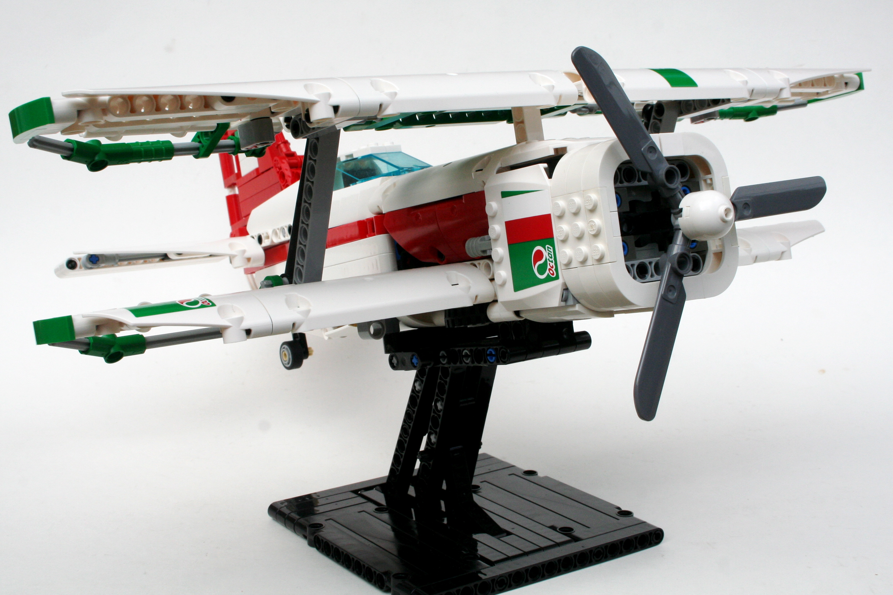
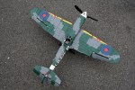
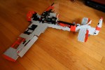
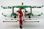
It was time for me to build another airplane, and I figured a0 small air racer would work well in the OCTAN colors. Right from the beginning, I was sure I wanted to make a biplane, and I wanted a radial engine (all real airplanes have propellers). From there everything was on the table. Off to designing.

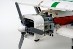
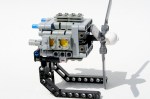
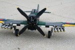
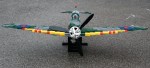
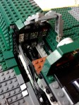
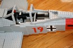
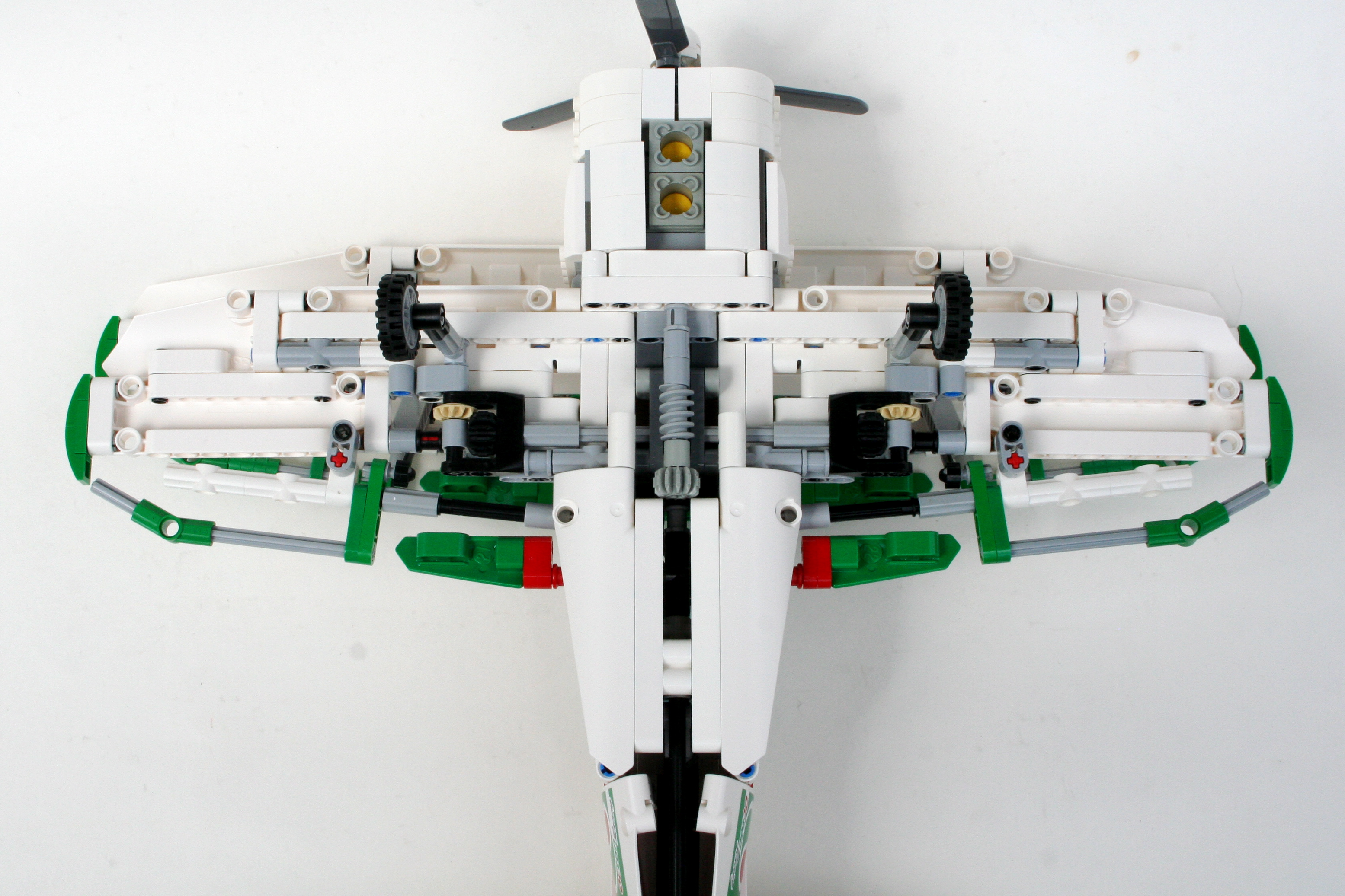
I started with the radial. It’s not quite a radial, but rather two perpendicular boxer 4 cylinder engines. Each bank of two cylinders are mounted in a different direction; up, down, port, and starboard, and are connect by one common crankshaft. The side banks are one stud forward, and the up and down banks rear, so all eight connecting rods can fit on a common 5l axle. Two engine crankshafts are mounted at each end. The motor spins well, and quite quickly, but the connection is not exactly “legal,” as the pins on the cylinders are a little stressed.

8 Cylinder Radial

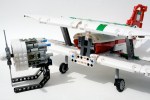
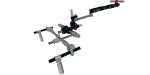
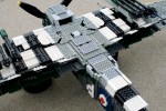
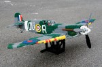
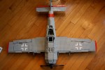
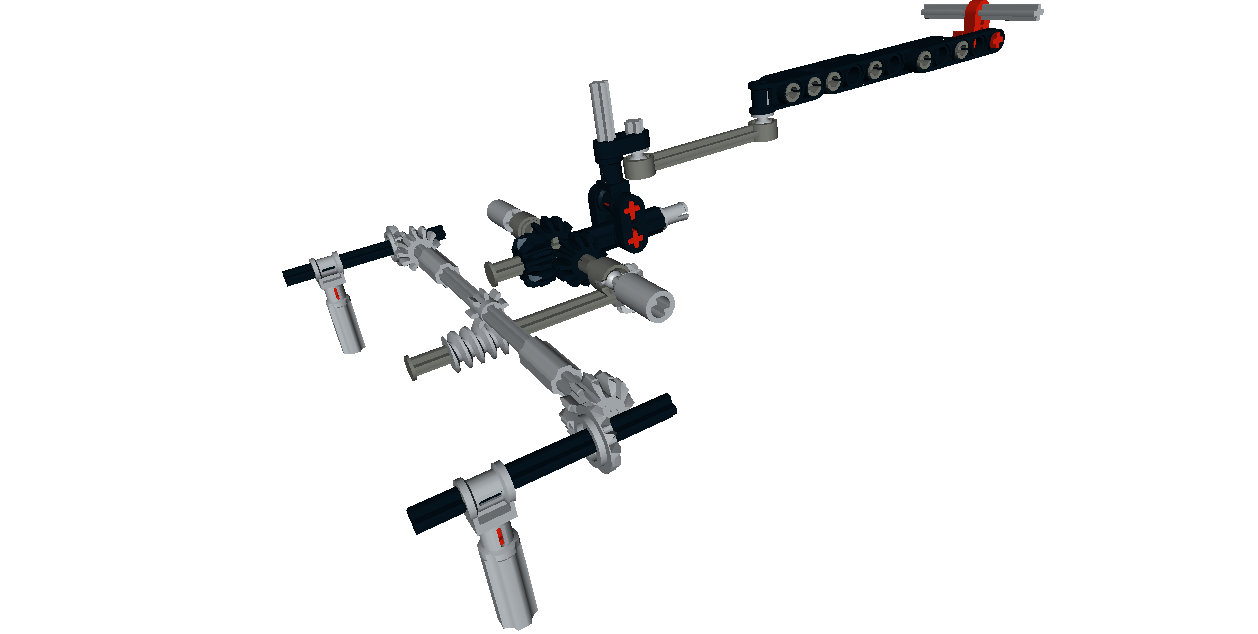
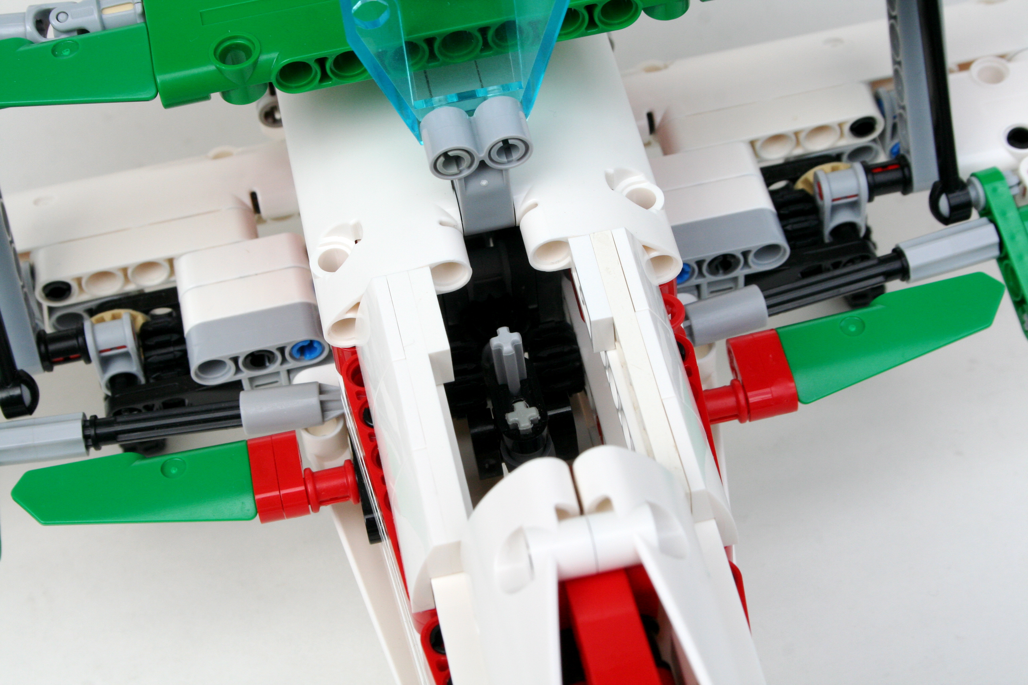
Working backwards, I attached the leading edges of the wings, and the worked on the landing gear. Being an air racer (even a biplane), it had to have retractable landing gear. I connected the two wide spaced legs with a simple axle and bevel joint, and added a worm gear to articulate the action. It is a simply solution, and it functions well.

Air Racer Bottom

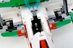
Just behind and above the worm gear is the joystick. The roll functions are connected to the bottom wing by gears, and the pitch function is connected by liftarms to the rear elevator. The rudder is fixed. The lower ailerons are connected to the upper ailerons by a simple 9L link. When you move the joystick, all four ailerons move. The cockpit is a little cramped, but when you are racing space is not a concern, only speed.

Air Racer Drive


Air Racer Cockpit

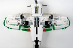
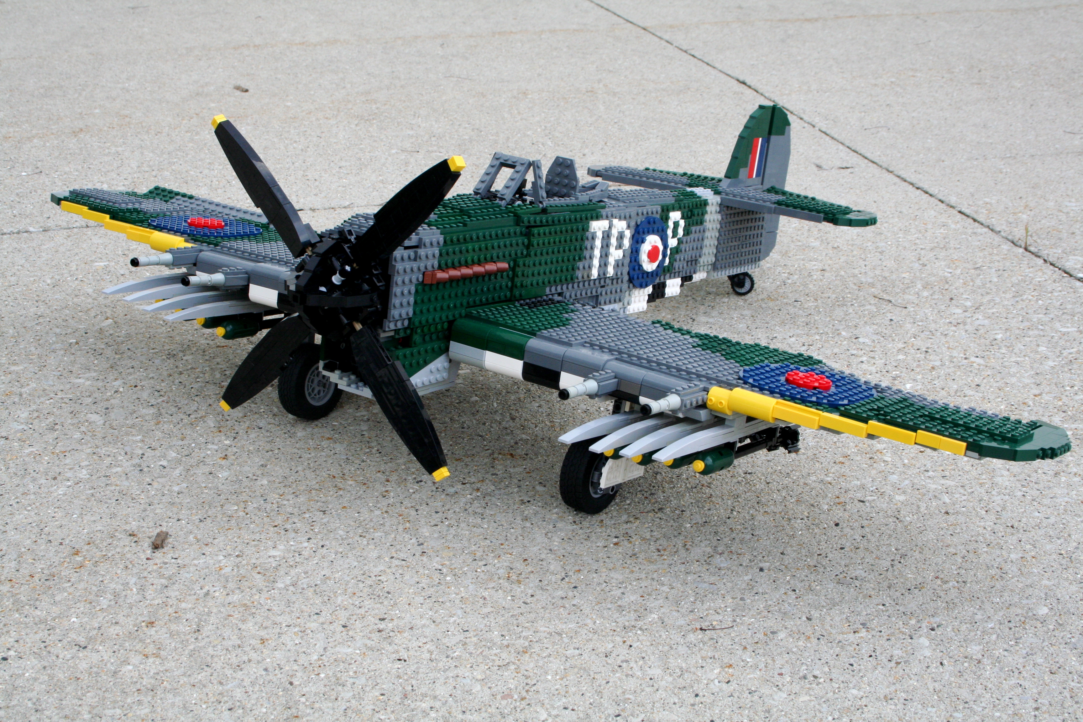
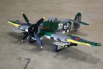
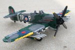
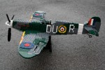
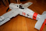
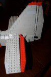
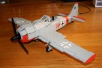
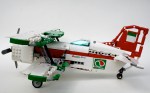
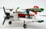
After the radial, the bodywork was the priority for the MOC. I have been slowly acquiring white and green parts over the last year. The airplane was designed as primarily white, with red and green accents. The red stripe worked well, as did the red tail, but I could not find a great way to incorporate the green. I added a little to the tips of the wings, and to the wing control surfaces. I used a couple more stickers that I had left over from set 60025, and the MOC was finished.

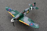
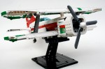
I was pleased with how the MOC turned out. The airplane looks strong, and the red and green make the white vibrant. I wish I could have found a better place to incorporate the green. The places it was added seems a little haphazard. The radial turned out great, but I feel a little bad about the illegal build. The landing gear works well, as do the control surfaces. I was pleased with how it turned out. Next up, maybe an OCTAN speedboat. Other ideas?

Happy building.


Advertisement

Hawker Typhoon MkIb


Two years ago I built the Spitfire MkIIa. It remains one of my more popular builds, and one of which I am still quite proud. It was not my first large plane, though when I completed it, I said it would be my last.

As my father would say, “never say never.”

Typhoon

The full gallery may be seen here.

I learned a lot of great things from the Spitfire. Large scale building is exciting, and challenging in that you have to think about significant structural considerations, placement, and shaping before and while your build.

With this in mind, I wanted to develop what I have learned, but allow myself the ability to take a large scale aircraft to the next level. I wanted to improve the function of the control surfaces, design my own propellor, use four Power Function channels, and use the boatload of Dark Green parts that I had recently acquired. I considered a number of airplanes, including doing the FW-190 again, but I finally settled on the Typhoon. Time to get building.

After some planning, I had my scale. 1/13 was an appropriate size for me to replicate the plane and its functions, while still keeping the plane from getting too large. This scale would also allow for LEGO wheels for the landing gear, and a worker able propellor spinner design. As I learned from the Spitfire, placement of large components needed to be done early, and placed in the MOC to its exact final location. As the structure of the fuselage and wings would be stressed heavily, large components could not get in the way. Once I placed the engine block, the landing gear, the power functions, and the control surfaces, I was able to start putting together the robust structures that would support the final plane. One of the major challenges of this plane was the outset landing gear on the wings. Because they were located 42 studs apart, the wings needed to be strong. But due the the space taken for the control surfaces, and the massive 24 cylinder power pack, the wings still sag a little under load.

The control surfaces were activated with strings with studs on each end. I found this to be a better system than the axle controls for the Spitfire. It kept the controls more smooth, and reduced the amount of play in the controls. The elevator and ailerons were controlled with the joystick, and the rudder was controlled by two foot pedals in the cockpit. The remaining functions were controlled via Power Functions. An XL motor powered the massive 38 stud diameter propellor, as well at the 24 cylinder Napier Sabre engine. A M motor controlled the pitch of the propellor. Another M motor powered the landing gear, and still another  adjusted the flaps. All four motor were mounted in the chin of the aircraft; I had to use that huge chin for something. The two IR receivers were mounted in under the windscreen, and the rechargeable battery was mounted behind the cockpit.

Finally, I had to make sure all the markings were accurate. Again, due the limits of dark green parts, it was not an easy task. I started with wings, and made sure to add invasion stripes, and work my way out to the tips. The roundels were a little different than the Spitfire, but were a little larger. The fuselage took a little work to make sure the panels could be easily removed, but I eventually got there. The fuselage roundel should have a yellow ring around the outside, but the strip is so small, I could not figure out a good way to do it.

The plane worked almost perfectly. The ailerons were a little sticky, but other wise everything else managed to work for an 8 hour shift at Brickworld. The plane was liked enough to be nominated for Best Air Ship. While it did not win, it was validation that the the model was a success.

Happy Building.

Spitfire Mk IIa


I am not a very ambitious person.  Sure I made it through college and graduate school, and have managed to work well in job for a while now, but for me to do something challenging, takes a lot of convincing.  It doesn’t happen often.  This project was a little bigger than it should have been, and I got in over my head.  This is not the first time this has happened (1, 2).  The project was interesting enough for me to keep moving forward, even after six months.  I present my 1:12 scale Spitfire Mk IIa.  I hope you enjoy the work.

View the full gallery here, and the work in progress gallery here.  Flickr set is here, and full instructions may be downloaded here.

Spitfire 3/4

First, the whole reason I did this project was because of the excellent Baby Twin Otter of Cpt. Postma completed two years ago.  If you have not yet seen this creation, take a look at the above link.  When I first saw this model, I went home a made his variable pitch propeller   This was the first step to my Spitfire, though at the time I did not know it.

I chose to do the Mk IIa version Spitfire for a couple of reasons.  First, the model had to have a three blade prop, because I wanted to use Cpt. Postma’s design.  Spitfires stopped using a three blade prop somewhere in the middle of the MkV series.  Second, I wanted to model a eight gun variant, rather than the cannon variant because I think it has a cleaner look, and I love the red and yellow leading edges on the eight gun variants.  Finally, while it would have been great to do a early model Spitfire with the dark tan camouflage  adding both the dark green and dark tan would have been too expensive, and even more ambitious.  I found a number of pictures of a certain MkIIa with all the features I wanted.  I chose a Spitfire flown by Lt. Tomas Vybiral, who was a Czech pilot with the French Air Force.  The plane was Spitfire P8081 when he flew for the British in Squadron No. 312.  It had simple markings for me to recreate, a camouflage pattern I would be able to do (read afford), and I found some good documents to help my modeling.

Next came the internal planning.  The Spitfire would have working ailerons  flaps, rudder, and elevators (with correlating pilot controls), prop, prop pitch, V-12 engine, and retracting landing gear, all within the 1:12 scale.  Once I had the dimensions calculated, I started placing things in a simple “placeholder” model on my floor.  I constructed the engine, the propeller spinner, pedal/joystick assembly and placed them in the placeholder.  Then I made the placeholder 3D.

It took two months to get the rest of the internals all set.  The required moving various parts of the 3D placeholder, and adding additional parts.  The joystick is connected through various liftarms to the rear elevator, and by axles to the ailerons   The pedals connected though a shaft to the rear rudder.  You can see the gears on the rudder.  The flaps have a simple lever in bottom left side of the cockpit.

The rest of the functions are controlled via Power Functions.  The small 8878 battery box is placed behind the cockpit, as is the IR receiver.  A PF M is housed under the V-12 and drives four mini linear actuators for the landing gear.  It is strong and simple, and works well.  It does not have the correct Spitfire landing gear geometry, but if someone can figure out a way to do it at this scale…well, I can’t figure it out.  A second PF M is used to power the propeller   It is placed directly behind the V-12.  Finally, a third PF M is placed behind the V-12, and works through a system of gears to power two mini linear actuators to move the pitch of the prop.  It’s messy inside, but it has everything I wanted.

After the internals, I had no idea how hard the rest of the Spitfire would be.  LEGO, you need to make more parts in Dark Green.  I know how selfish that sounds, but it would have been more helpful.  Thank to some newer sets, like the 10226 Sopwith Camel, and the  21016 Sungnyemun, it made it much more possible, but still limited me in many places.  I spent the next four months acquiring parts, and placing small plates over the rest of the plane.  With some help on the roundels from Dieterr89, it eventually came together.   The bodywork took a long time.  Too long.  And the lack of some parts in Dark Green forced me to make some concessions.  The canopy frame should be all Dark Green, but it was not going to happen with what is available.  The camouflage is not as clean as I would have liked, and there are some abrupt steps where some plate limitations made the transition for one part to another not smooth enough, such as on the rear fuselage.  Also, try as I might, I could not get the leading edge of the wing to be perfect.  The dihedral did not help either, nor did the yellow leading edge.  Also, the gaps between the control surfaces and the fixed part of the wing and stabilizer was more than I would have liked.  But this has happened before.

I am please with how it turned out, but there are some parts that I wish would be better.  I never seem to remember this when I start a project in this scale, but free moving functions just do not operate well as you hope when you keep adding parts.  The control surfaces work, but they could be smoother and lighter.  The powered functions worked flawlessly. I was very please with the way the markings turned out.  They are not as flush with the plane as painting would cause you to believe, but they make the Spitfire clearly identifiable.

My father would always tell me “never say never,” but it may be a long time before I do another large plane.  But I guess I said that back in 2008.

I hope you enjoy.  Thanks for reading.

FW-190a3 Instructions


I have a love hate relationship with LEGO instructions.  On one hand, I think they provide a great service to other builders.  This has become clear with my 8081 4×4, which has been much more popular than I could have imagined, in part because I have published instructions.  Builders like to know how other builders come up with ideas to solve problems.  But on the other hand, instructions are a lot of work to produce.  Especially if they require some rendering program.  I guess I could charge people for access to my instructions, but that seems to take away from the access to ideas that I like to support in the LEGO community.

With that I present instructions for my FW-190a3.  The FW-190 needs no introduction.  It it still one of my more favorite airplanes, so I thought I would make a minifig version, and publish instructions for it.  As with all of my instructions, links can be found on my Building Instruction page.

Instructions can be found here.

Happy Building.

Focke-Wulf FW-190 a5


I start most of my projects because I see something brilliant by another builder, and then I decided to develop this idea, or give the idea little more substance.  After discovering a great two row radial, I wanted to give the engine a body.  It had also been a long time since I had done a large project.

I chose to make the FW-190 for a couple of reasons.  First, it had a radial.  OK, 14 cylinders in the plane, and mine would only have 12, but it was close enough.  Second, it was one of my favorire plane of WWII.  Third, the body work would not present too many challenges.  I set to work.  I had to get the scale right, and start placing some of the plane’s extremities, so I would have a good idea where to place all the parts that I would build.

Once everything was placed, I had to figure out how I was going to do all the control surfaces.  This started with figuring out the joystick, and the rudders.  The joystick was a simple design driving side to side movements out the front by an axle to gears for the ailerons.  When the joystick was moved front to back, a link all the way to the rear elevator was activated.  I mounted the foot pedals on a simple pivot connected by gears to the rear rudder.  Flaps, with a simple activating lever, were also installed.  The cockpit was pretty full.

With a project this size, it took a great deal of work to get the shaping of the plane to work right.  I used half stud offsets to get the fuselage correct, and spent a lot of time on the wings.   Because the cockpit had a lot of activating levers, a lot of work went into the area around here.  Adding the opening canopy did not help things.  I added brick built markings, worked on the coloring, and spent some time adding guns and other details.  The model was done.

Brickshelf.com gallery is here.

It’s been three years since I have built this plane, but I needed a little motivation to help me with another similar project.  It was good for me to remember how much I enjoyed this project, even though it took a lot of time and energy.  Stay tuned for the next big plane.