There is a part of me that finds LEGO 42098 a little gimmicky: buy this truck that fits 5 cars but comes with 1 so you you build or buy more to fill the truck. But, these wheel arches are so awesome that I am going to do just that.
Full gallery including instructions may found here.
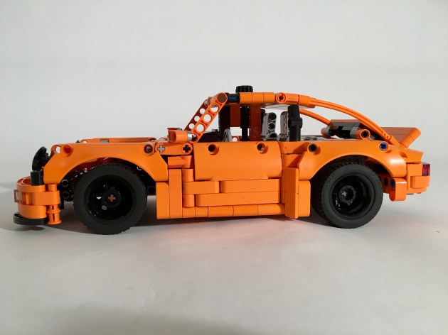
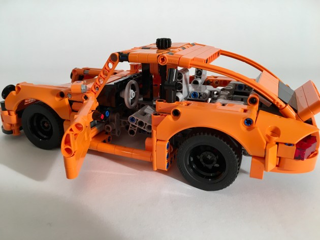
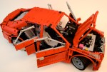
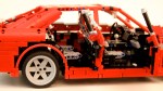
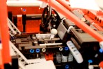
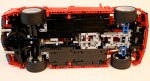
After a rough first draft it was clear I was going to be able to steering and a Flat 6 into the car at a scale that would work for 42098, so most of the early work was on figuring out the shape of the car. I knew the car was going to be orange, and I wanted the little ducktail spoiler, so I modeled the car after the 964 version of the Porsche 911. The rear differential is placed two studs in front of the rear axle to allow for more room for the rear engine. I kept the normal LEGO engine parts rather than an axle engine like in 42098. The steering is simple in all in front of the driveline.
The body work continued to take the most time. I used a great 911 MOC from Paave for many ideas including the seats and the front hood. Eventually, it all came together, after a lot of work on the doors, the roof, and the rear deck. The 911 is a beautiful car and getting all the details is so tricky. I almost feel bad for how critical I was of LEGO 42056. Almost…
One thing you will notice is my use of both the 43mm and the 49mm tires for the rear of the car. I go back and forth on which ones I like best. Also, there was no way is was going to use the skinny 43mm tires for the front. They look silly.
This little car worked great, and functioned as intended. The shaping was off a little particularly with the rear quarter panels, the roofline, and the front headlights. But the shape of the 911 is so iconic that get all the details that have been refine over 50ish years is tricky. Either way if fits on the back of 42098.
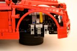
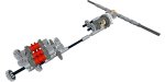
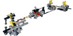
After my last helicopter, I wanted to build one that was more basic. This one would simple, small, colorful, and would make use of the excellent blades from set 9396. I wanted to do something like the Sea King, but with a Fenestron tail. I used a HH-52 as a basis for the scale. I built a mock-up of the scale, and started making the gearbox for the helicopter. The main rotor could be operated from a gear on the left of the aircraft. Two changeovers located next to the landing gear pods could be engaged to drive the land gear (up or down, on left) and the winch (up or down, on right). The main rotor was connected to the Fenstron fan at the rear. Both the landing gear and the winch are driven by worm gears, so they would stay locked when the changeovers were in neutral.
The gearbox is mounted in the bottom of the helicopter directly under the rotor. The landing gear mechanism moves forward with the pilot and co-pilot seats directly on top (I love those new panels). The winch gear moves aft, and drives a simple string spool. The compact driveline keeps enough space for a full cabin. There is enough room to add a battery box, and a M motor to power the rotor.
The body work came together quickly with the exception of the rear doors. I wanted to add two sliding doors with windows, and based on the color scheme of the helicopter, they had a to be white. After six drafts, I finally came up with a solution that was doable. They are not perfect, but all the other designs had windows that were comically small, or too low in on the body. Unfortunate, the design calls for six white rare parts. The rest of the bodywork turned out well. The nose, while a little clunky, looked how I wanted. The top area looked good with the three engine exhausts, and the six bladed rotor, while overdone, fit perfectly. Oh, and with clever pin placement, you can fold the rotor back towards the tail. The tail looked sharp with the ducted fan. The vertical stabilizer looked empty, but that’s a problem for all LEGO Technic aircraft with the exception of 42040 (maybe).
The helicopter worked great, though a clutch for the gearbox would have been nice. I was pleased with the bodywork of the helicopter, and the colors worked well; maybe grey and orange would be great on a rebuild. I would have lived to have a cleaner design for the wheel pods, but it worked well enough. It was a good swooshable design, as I found playing with the helicopter extensively. Now I need to make a scale Coast Guard ship on which the helicopter can land. Maybe next year.
About 3 months ago I purchased a set of four Fischertechnik tires from ebricks.ru. After seeing a review of them by RM8, I reached out to him, and he mailed me a set. After a little time, I finally have something to show with them.
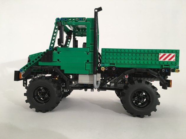
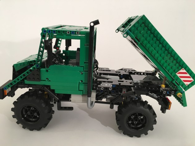
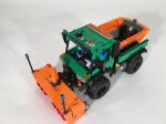
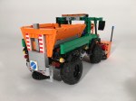
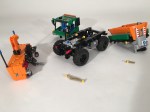
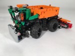
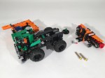
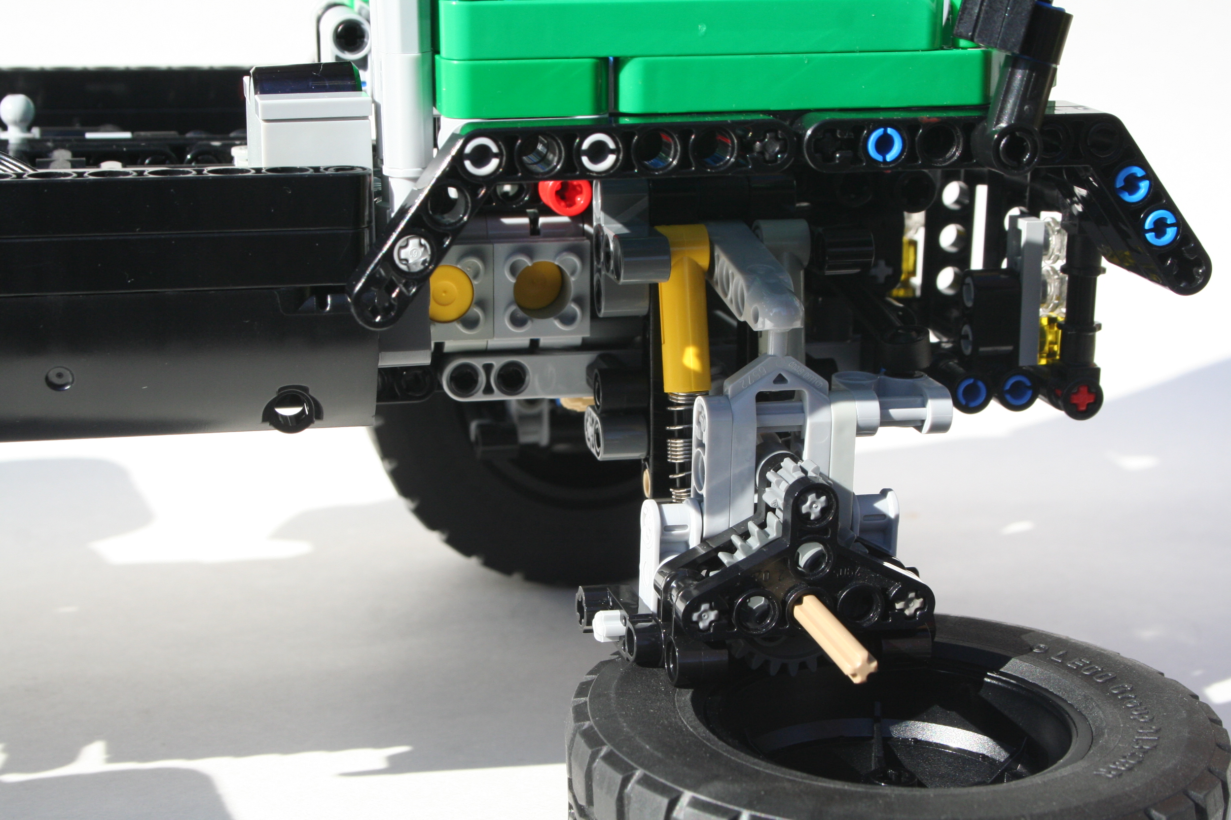
After playing with a number of ideas, I decided to do another Unimog. It’s easy to motivate myself to build a vehicle I love. This time, I wanted to do the unloved U90 (418) version. It was not a terribly successful version, as many find the hood…not one of the best. But few people have built this version, so I was up for it. I put to to a vote on Eurobricks, and the decision was to build it in green. Off I went.
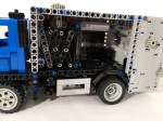
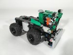
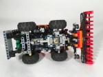
The scale required a 27 stud wheelbase and a 19 stud width. I built the front and rear axles and tied them together. Through a couple of edits, I finally added the suspension and figured out how to get portal axles into the truck. The Power Functions XL motor was mounted just over and in front of the rear axle driving power to all four wheels. The Servo motor was placed directly ahead of the XL for the front axle steering. I added a four cylinder fake engine over the front axle. The rechargeable battery box was placed over the rear axle.
The suspension is a live axle setup, with four hard shock absorbers at each corner. Each wheel has about 2 studs of travel. Not much for a Unimog, but enough for a 418. At this point I started a draft of the cab, and a draft of the bed. At this point the truck had an identity crisis. Move forward with green or find another option.
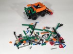
Building LEGO Technic with green is not the easiest. The color lacks 1×5 and 1×11 beams. Both of the these parts would be needed for the bed and the cab. I could make some things work for the 1×11 in the hood, but there was no other option (read, inexpensive option) for the 1x5s needed for the bed. I toyed with other colors for the bodywork; orange, white, blue, yellow. None of them had the right pop I was looking for. Other than the orange, but, as other have said, orange has been done too many times. Then it dawned on me, “why not use plates?” I had my solution. With one bricklink order, I was done.
The truck drives well, and is easily controllable. The front portal axle can use a little strengthening, so serious trial abilities are lacking with this truck. Both the bed and the cab can be easily removed. I ran out of space for a ram to elevate the bed, but it can tilt three ways. I was pleased with how the truck turned out. It looks great. The driveline coule use some improvements, so I will make those improvements on the next truck.
My favorite vehicles to build are garbage trucks (Ok, maybe trial trucks). I enjoy the many functions that I can create. I enjoy the diversity of shapes, sizes and colors, and I enjoy how ubiquitous they are. But I have not built many. So it was time to fix that.
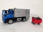
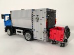
I was originally going to do a large scale truck, but as my temporal limitations are becoming ever more apparent, I decided to do something smaller this time. The 13 stud wide truck is popular in the Technic community, so I decided to go with that. I very much enjoy the Volvo FE, so that was my truck. Since my last truck was one with three axles and Power Functions, this one would have two axles and be manually controlled.
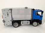
I searched high and low for garbage box that would work well: Gesink-Norba, Heil, McNeilius, EZ-Pak, Dennis-Eagle, Ros Roca. All required a compactor that would need a round base for the trash to collect. Curves are hard to do in LEGO. I had some trouble with refuse compaction cycle working well on the Axor due to the floor curve on the hopper. I wanted a compaction cycle that was more simple and more reliable. So I designed my own.
It’s dead simple.
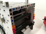
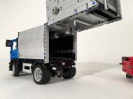
There is a angled elevator in the hopper that goes straight up and down. The center gear on the outside of the hopper that moves the elevator. When refuse is placed on the elevator and lifted, the refuse will fall over an internal wall at the top of the cycle. The refuse falls into the compaction bin, until the rear hopper is opened. Bigger parts sometimes gets stuck on the cross axle.
Inside the compaction bin, is an extraction plate. Turn the gear down near the front left wheel, and you drive a mLA to move the internal extraction plate. Everything works well for small LEGO refuse parts. I built the side of the compaction bin with slopes and tiles. After a number of panel attempts, this one seemed to be the best looking option. I very much enjoy the shape.
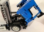
Since I had a little more internal room, I added a driveline to the truck. A rear differential powers a small fake inline 2 cylinder engine under the cab. To check it out, the cab tilts forward. The steering axle serves as a friction connector so the cab does not open unless you intend it to tilt. The doors open, and the bodywork was designed to mirror the Volvo FE 2011 body style. I built a small red refuse bin to show off the functions of the truck.
This may be my favorite build of the year. All the functions work perfectly, and the model looks great. I think I could add a tilting bin function, and add another mLA to give more strength to the extraction plate, but other than that I am not sure I would change anything. I will keep this one built for a while.
I participate in only some of the contests that are available in the online LEGO community. I generally participate if it meets the following criteria: Is the challenge within my competencies? Does the contest align with other responsibilities/projects to which I have already committed? Can I be competitive? Frankly, it is the last question that often stops me. The preceding two questions determine my limitations, and considering how good many other builders are it is not often I participate. With this in mind, I decided to enter the Eurobricks Technic Challenge 9 (nine already!?).
Edit 2016.02.16 : The contest has completed, and this Model came in second! See the results page here, and all the votes here. Thanks to Eurobricks for the contest.
A full gallery with Instructions can be found here.
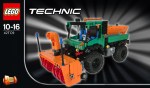
What interested me in this contest was the constraints, and to a lesser extent the topic. the constraints stipulated that both MOCs had to fit within 10,000 cubic studs. I got out my calulators, and started playing with numbers. I was hooked. Additionally, building one MOC is hard, and building two from the same parts seemed very hard. It was something I had never done, and only a few builders can develop a good B or C model. The planning stage would be critical. Both models would have to be planned together right from the beginning. I toyed with a Combine/Tractor, and a Pipelayer/Crane, and even a Airplane/Boat. With each of these designs, I realized I would be using too much space with a long appendage, such as the Combine’s implement, or the Pipelayer’s arm. The cubic studs required something more…cube shaped. I eventually settled on a Snowblower and a Tractor. Both were a little more square and had similar components (wheels, engines, colors, chain links). I knew I would need to build both together, and multiple renditions would be needed. I was ready to start building.
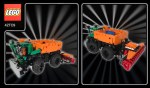
Pretty early, I settled on 17x17x34 studs for the Snowblower. I challenged myself to include steering, a working blower, and a working salt spreader. I build the basics of the blower implement right away, complete with rotation coming from the truck drive. On the rear, I added an implement lift using a worm gear setup, and a quick link to the truck . Next, I worked on the chassis of the truck. I added portal axles, because I could not get the 5L wheel axles to say connected to the differential. This also helped to clear the front PTO from the steering function, which was linked directly to a HOG gear on top of the cabin. The salt spreader needed a take-off gear for the conveyor belt, and the discharge plate would be driven separately from the rear differential. The mechanics were set. I then worked on the cab. I made sure the cab, the blower, and the spreader could be easily removed by removing up to four pins for each. It’s a fun modular function that allow for other attachments.
I first made a pile of all the parts used for the truck while it was still built, and made a first draft of the tractor. Based on the parts of the Snowblower, the tractor would have four wheels, a 2 cylinder engine, and something with a whole bunch of 3×3 round, red, liftarms. I first modeled it after a John Deere 7R series, but realized this would leave me with too many left over parts. I then tried modeling it after a Claas Saddletrac. This seemed to be a better fit. I then took apart the Snowblower, making instructions as I went. I then used these parts to make the official model B. Over the course of a week, I made many revisions.
Both models worked well, as none of the feature are too complicated. I was pleased with the A model as everything functioned as it should, and it looked great. The tractor was simple, and it’s simple functions worked well. I was pleased with how it all turned out. It was great working with a limited number of parts for the B model, but I would prefer to clean up the look of the tractor a little better. This was a great little contest. I loved the restriction of the cubit studs, and I loved having to make a MOC with a defined group of parts. Now let’s see how the voting shakes out.
There are not many projects I start that I do not finish. I can count a couple. But, sometimes there are projects that take a long time to complete. I either loose motivation, lack parts (read budget), or find something else to do. If I were wise, I would toss the project, and move on to something better. But there is value to trudging through the slog and completing something difficult. The Spitfire is a great example of this. The Audi Allroad has been on The Queue for about 16 months, and it’s finally done.
After completing the OCTAN F1, I thought I could use the suspension for an all-wheel drive car. I was sure I could make the front suspension with steering work at this scale.
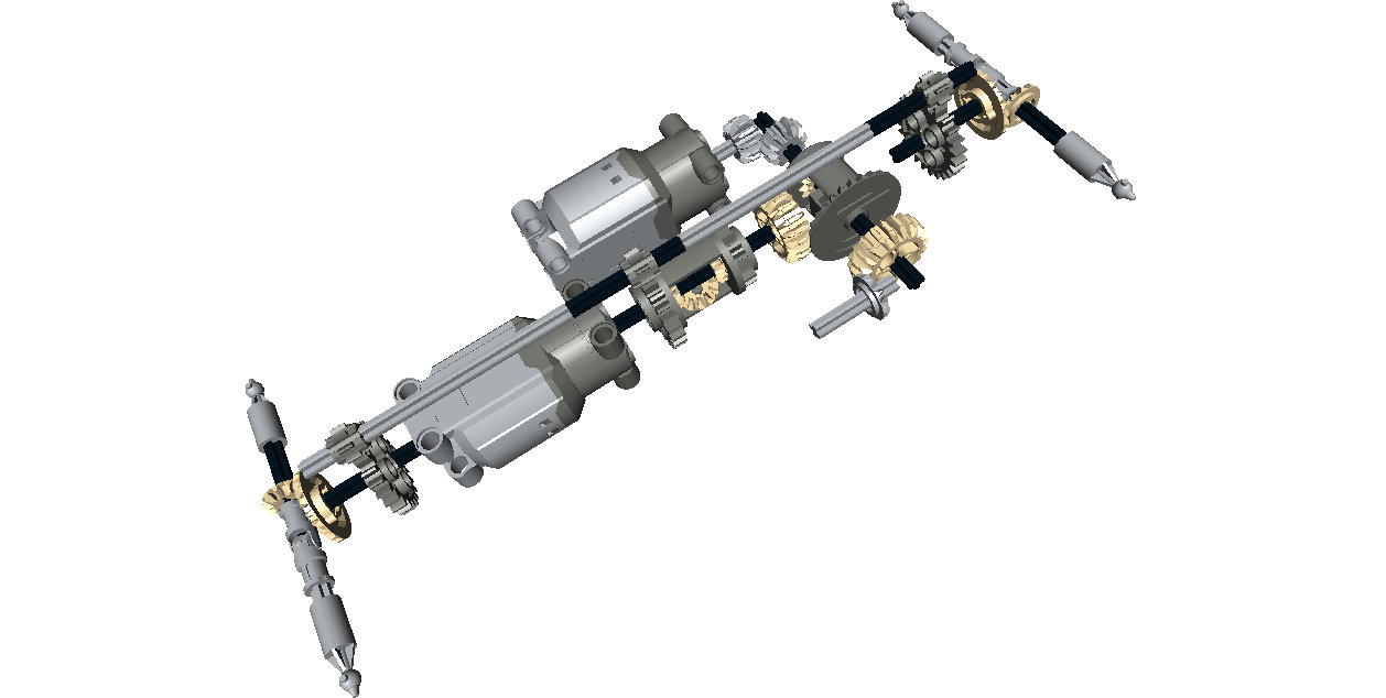
I wanted it to have another fun feature, so using a bunch of differentials, I developed a simple three speed transmission. Three power functions motors are connected via two differentials which connect to the drive axles. Each differential acts as a subtractor between each motor. When one motor is running, the power moves through two differentials, and the car moves slowly. When two motors are running, the power moves through one differential, and it’s a little faster, and when all three motors are running the car is running the fastest as no differentials are splitting the power. I got it to work, and within a day, I had a working chassis.
Once this was done, the MOC sat on my desk for a long time. This past fall, Thirdwiggville welcomed another citizen to the village, and this gave me lots of time late at night to get back to working on this project. I spent a couple of weeks working on the body work with the perspective of “finish this.” So the body work could use a little more polishing; doors, mirrors, better lines, maybe an interior. But I was happy to finally get this done.
The MOC worked well. The suspension functions quite well at this scale, and the transmission was simple and effective. It could be a little quicker, but I was not going to make a substantial gearing change after the MOC was built.
Two final thoughts. I need to stop building supercars because they take a lot of time and effort for me, and I find little motivation for the body work; I do not think the body work looks good, and I lack motivation to work on it. Second, I needed to test the driveline earlier in the build process. I spend too much time fiddling with gear ratios after everything was build. But this project is done, and I am happy it is.
My favorite constructions vehicles are feller bunchers. The wheeled ones. So I am naturally inclined to make them. I built a small one; I built a large one. I wanted to build a medium one, but I figured I should get out of the box. At least this time.
The full gallery may be seen here, and instructions may be found here.
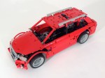
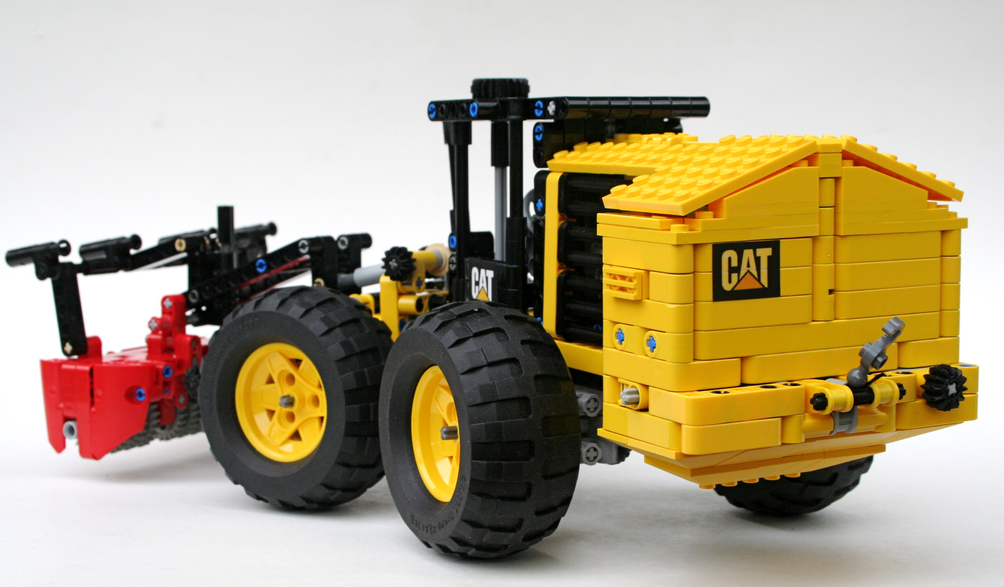
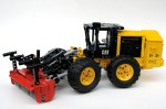
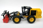
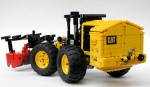
The CAT 586C is a site prep tractor. Forgive me for simplifying the work done by the engineers, but the tractor is basically a 573C with a new implement for site preparation, rather than felling. As always, I stared with scaling the full tractor from CAT’s website, and finding a size that would work well with tires, features, and aesthetics. Then I started building.
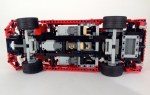
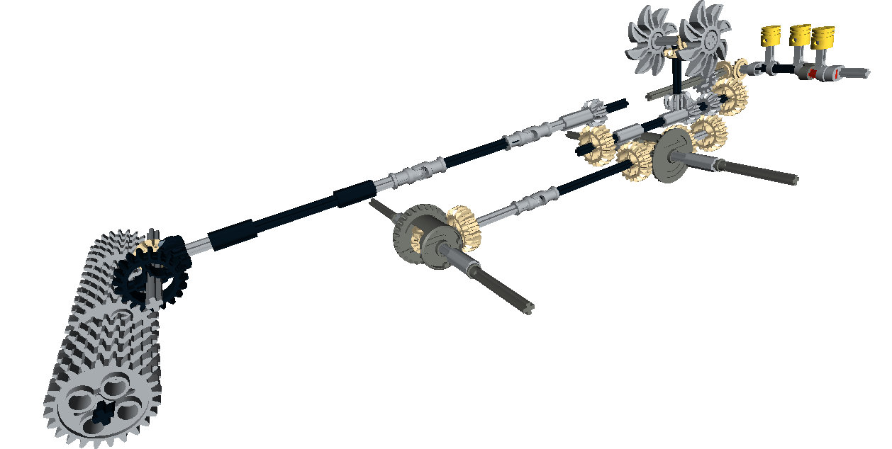
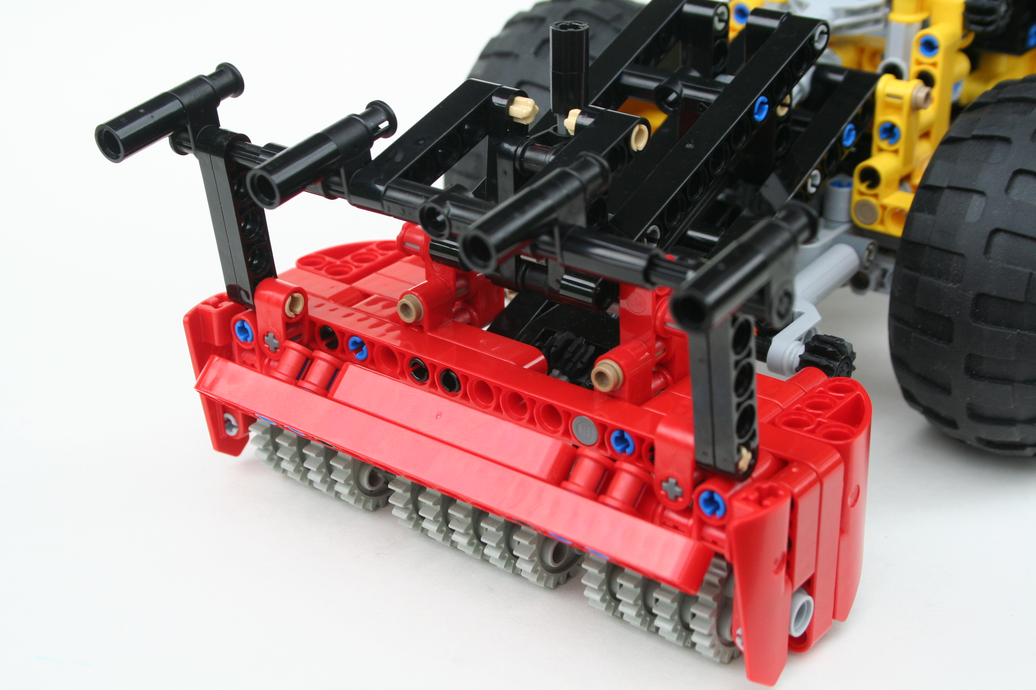
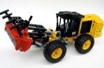
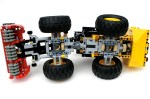
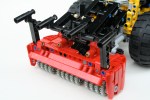
I started with the chassis, to get a sense of the size and the layout. I had a good idea of all the features I would want, and I knew some planning would be required. I then finished the mulcher (implement), which is basically a rotating drum with lots of teeth on it. I used a bunch of 24 tooth gears, and connected them to a rotating driveshaft. The chassis was built with four wheel drive, and was connected to the mulcher driveshaft through a series of gears to increase the speed of the drum.
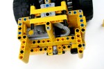
Then on to the back of the tractor. Feller bunchers and site prep tractors all have their engines in the back; pretty normal for large tractors with large front implements. But to get the weight as far back as possible, the engine is mounted transversely. This presented a couple of challenges for me. I mounted a I-3 engine on the left in the rear with simple gearbox geared up to connect it to the drivetrain. Just in front of the motor are the two cooling fans, which are also driven by the drivetrain. These are also geared up. For those of you keeping score at home, the drivetrain gears up three separate functions, so rolling the MOC on the floor causes a nice whizzing sound.
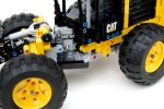
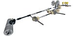
I added some additional features that mirror the real tractor. First, over the mulcher there is a guide bar that allows the tractor to push trees and shrubs down toward the mulcher. In my MOC this is accomplished by a simple worm gear mechanism. Second, I added a small winch on the rear to get the tractor out of sticky situations. Finally, a small mulching door was installed to allow for more or less entry to the mulcher, again just like the real tractor.
The tractor worked well. Functions were smooth, and required no maintenance during play. The many controls on the front were a little dense, and this caused some finger congestion. The number of rotational features connected to the drivetrain made rolling on the floor a little strained. Thought, this kept the MOC from rolling off the table into a lot of pieces. Everything worked well enough, so maybe it is time to make another feller in this scale. Not today, I still have a lot of other projects to complete first.
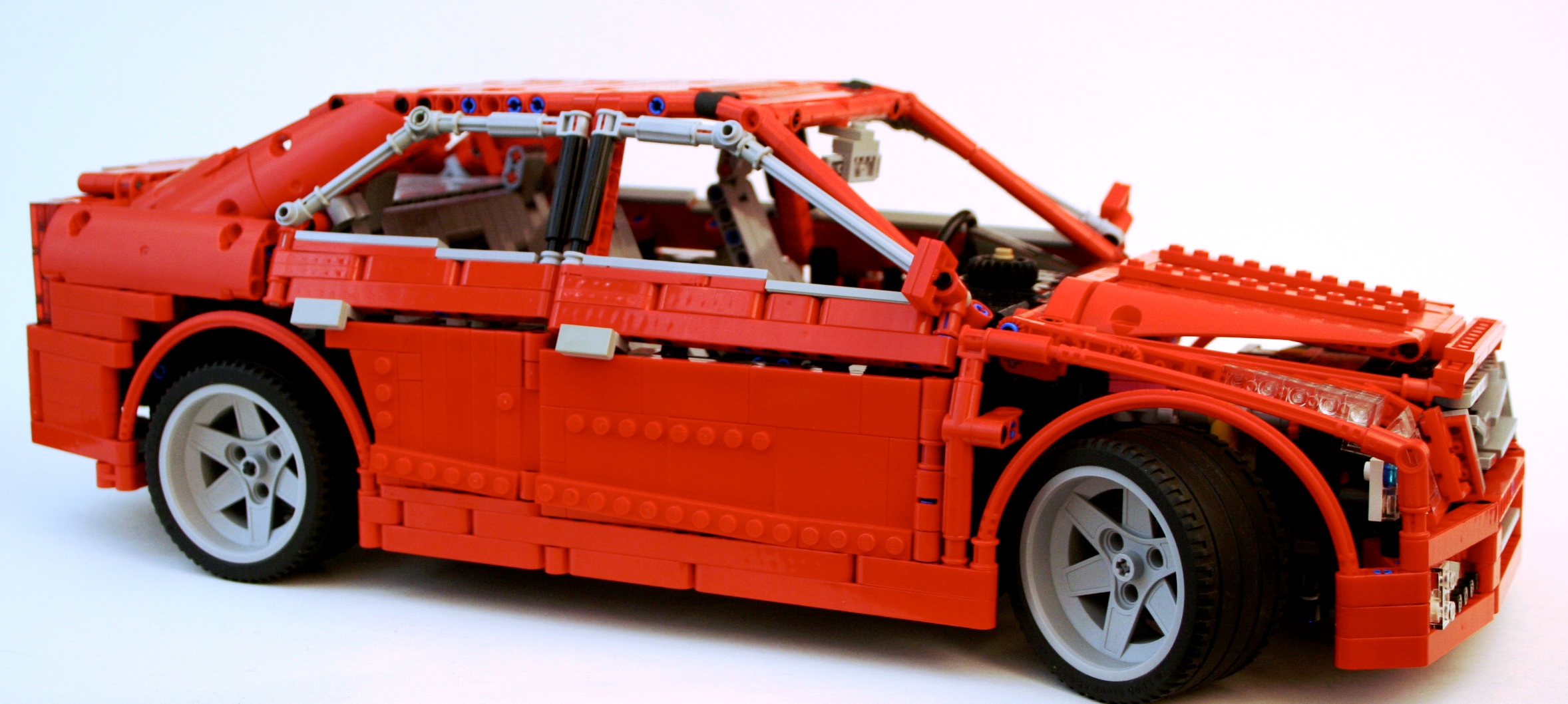
A while ago I decided I was going to do a proper new school supercar. Something with all the features that are to be expected in the LEGO Technic Community. You know what they are; suspension, a gearbox, opening doors, a working engine, steering, and something fast looking. Probably red. It was time to test my chops and throw my hat into the ring.
The full gallery can be viewed here, and instructions may be purchased for $9 USD. Partlist
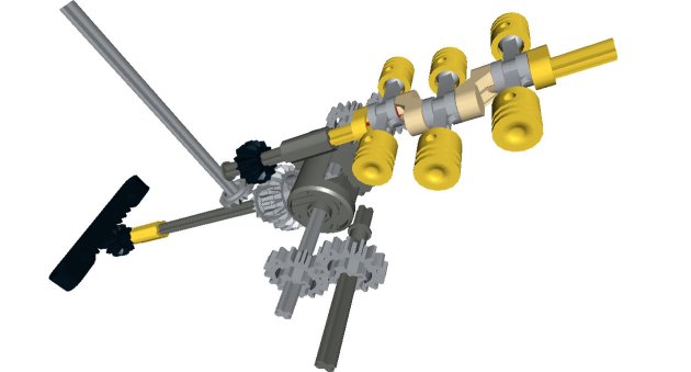
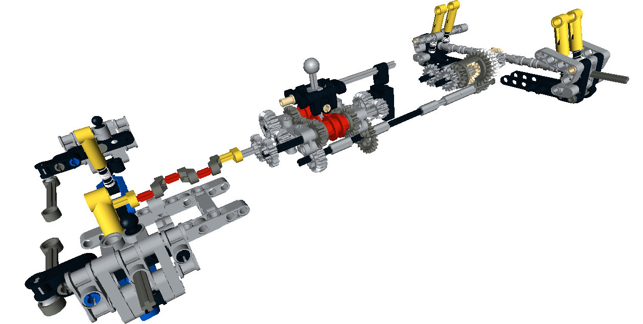
It has been a long time since I have built a supercar. While I enjoy many of the cars others make, I long for exceptional creativity in suspension design, gearboxes, and body style. It was time for me to build another one and contribute to these areas. About two years ago I set out to create a six speed gearbox that would have a more realistic gear change movement. I tried linkages, springs, and so many gears. In a bit of a breakthrough, I offset the two outside changeovers vertically by 1/2 stud. This allowed for the changeover lever to connect all three changeovers as it rotated from a single center pivot point. Once this design was completed, it needed a home.
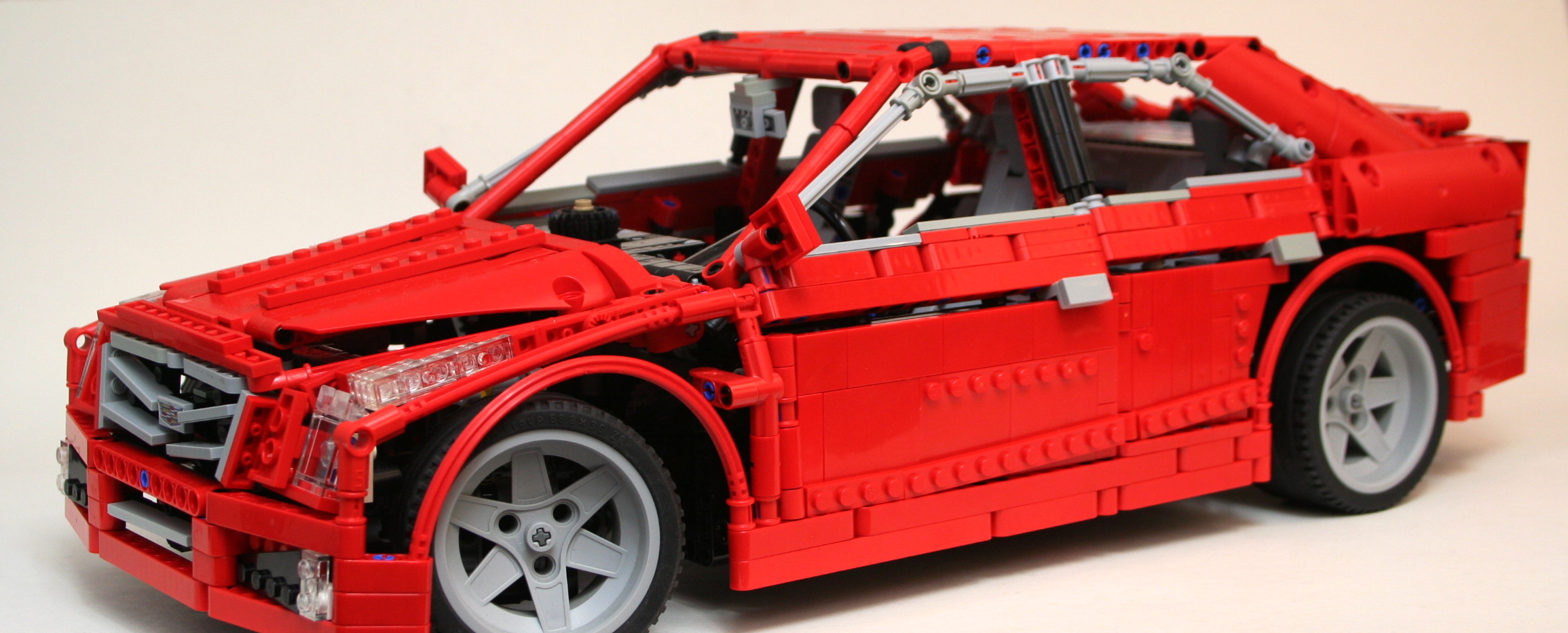
I have a preference for sedans rather than coupes. Plus too many two-door supercars have been created. Forgive the slight nationalism, but I thought it would be fun to do an American sports sedan, so a Cadillac was the best choice since the demise of my beloved Lincoln LS. The ATS was new, and at the scale would be a little more manageable than the CTS. I worked a little on the scale of the car. Some parts would be a challenge to convey the look, but I was ready to start building.
I started with the front suspension. The new suspension arms allowed for a short/long arm setup. The two different arm designs allowed for a increasing negative camber as the suspension moved through its travel. Additionally, the pivot points on the steering hub allowed for a kingpin inclination to provide an improved caster angle. Finally, I added Ackerman geometry to the steering link. After some work mounting the suspension, and the rack and pinon steering, I had the front suspension done.
The rear suspension was more simple, but still had some unique features. While the real ATS uses a 5 link setup in the rear, I was not too impressed with the results I came up with as too much flex was found at the wheel. I started with a transversely mounted limited slip differential that I have used before. This connected directly to the two half-shafts for the rear wheels. I applied a short/long arm setup for the rear suspension so the tires would keep their contact patch as the body would roll through a corner. Like the front, this created increasing negative camber as the suspension moved through its travel. Normal in real cars, not often replicated in LEGO.
Tying all of these parts together was a little bit of a challenge. I wanted the steering wheel to be connected to the steering as well as a HOG knob on the dashboard. In addition, the doors, trunk, and hood should all open. Naturally, the car had to have a spare tire, and various engine options which could be easily removed. The chassis had to be stiff enough for the suspension to function well. Packing this all together took some time. About 9 months, but who is counting?
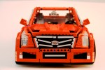
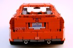
But what took the most time was the body work. This is the part for which I have little motivation, and the important part that would identify the car as an ATS. I had a lot of work to do. And my palmares have not trained me well for this task. After major parts were placed, and the dimension were set (37 stud Wheelbase, 60 stud Length, 25 stud Width), I worked on one section at a time. As the front bumper was part of the chassis, this part was developed early. As did the rear bumper. The headlights are unique for the ATS, so this was done early as well. After the roof was placed I worked on the trunk, which came together rather easily. I worked on the hood of the car, and after two designs I was happy with the result. I then worked on the grill, and after tinkering with a couple of SNOT techniques, I was able to get most of the distinctive Cadillac grill in my design.
Then off to the doors. I made seven designs. Most sedans these days have various creases that identify their sedan as different than any other sedan. You will notice the ATS has two, one on the bottom that rises slowly to the rear, and one midway up to the windows that moves along the length of the car from the hood to the trunk. The top line was accomplished by having the angle for the windows start a little lower on the front door and higher by a 1/2 stud on the rear door. The bottom crease was added by attaching some angled plates to the bottom of both doors, which cant slightly inward. Finally, both doors have an upper pivot point that is 1/2 stud inboard to bring the upper part of the doors toward the center of the car. Once I got a design I liked, I had to bring it all together to make sure everything fit well. I adjusted the roof, modified the hood, tightened up the dashboard connection to the doors, and made some changes to the rear quarter panels. There were still some areas where improvement could be made, but I was running out of ideas. I was pleased with the result. Pleased enough to say I was done.
All in all, I was pleased with the result of the car. As this is my first studless supercar, I was happy with how it turned out. The functions were up to my standards, and nothing was compromised as the car came together. While I was overwhelmed with the bodywork, I was pleased with how it turned out. Because it took me a long time to get it to work, it may be a long time before I do another one. I was happy I did a sedan, and hopefully a new moniker can begin in the LEGO community. #supersedan.
On December 18th, 2004 I bought 8386 here in Cologne, Germany. It was the first LEGO set I bought in 7 years, and thus was the end of my Dark Ages. It was my return to LEGO. Today marks ten years since I bought this set. This is a celebration of that event 10 years ago.
A lot has happened in the last ten years. When I think about that time I pause to reflect on where I have come. I have lived in 10 different places, including three states, had a number of different jobs, and increased my family unit by a factor of three. But people don’t come to this website to read about me, they come for LEGO. Over the last ten years we have gained much. The Technic line has improved both in terms of functional abilities, but also in the frequency and quantity of models offered. We have gained Power Functions. We have Linear Actuators, CV joints, more suspension parts, and so many more wheel options. We have favorite elements that did not exist ten years ago. Colors now include green, blue, white, and orange. LEGO made a Unimog. Bricklink started not much more than 10 years ago. Let that sink in for a moment. All of these developments have made so much of my building possible. It only makes sense to celebrate with a MOD of the set that reminds me of my return.
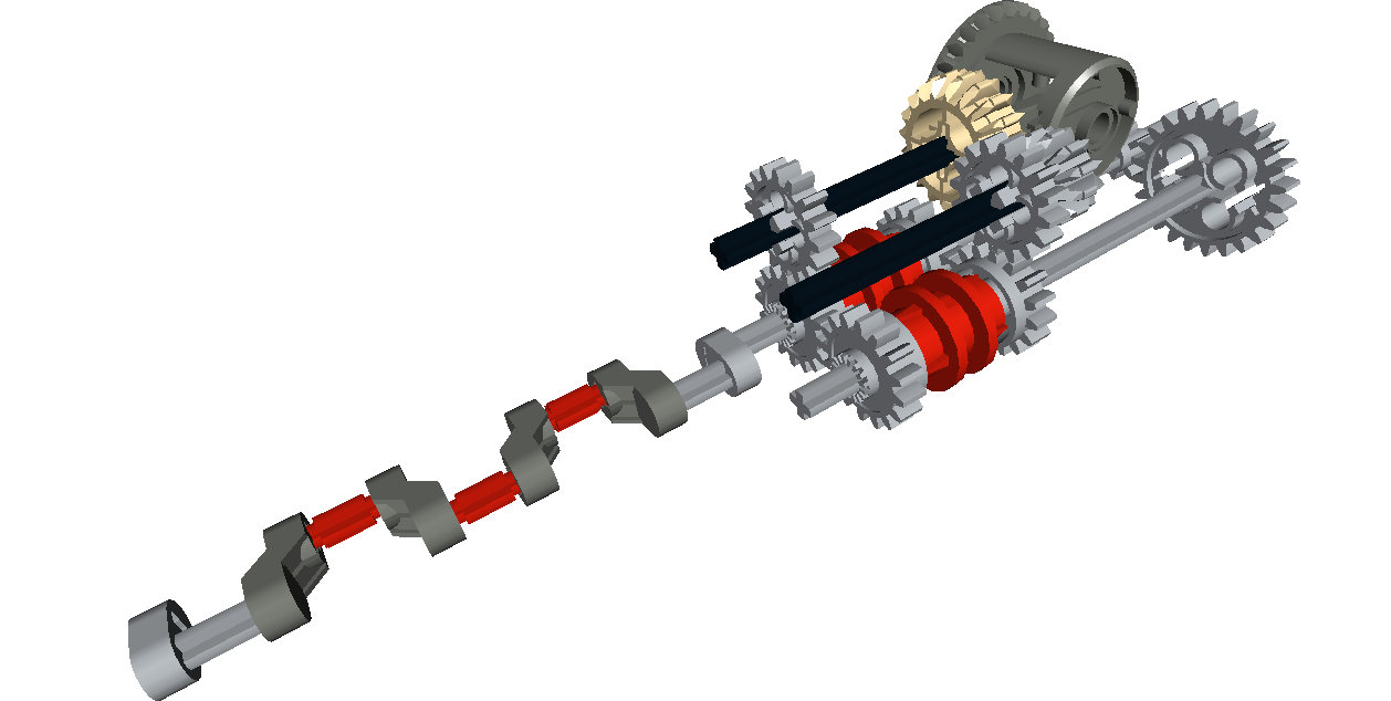
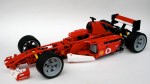
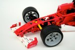
8386 was a rather basic set. It was modeled after the F2004 car #1 or #2 of the 2004 Scuderia Ferrari team through a licensing agreement with Ferrari. The cars were rather successful during the 2004 season at the hands Michael Schumacher and Rubens Barrichello. 8386 included working steering, a working V-10, and a removable engine cover. And that’s about it. Oh, and a lot of stickers. As I did with the 8081 4×4 my goal was to keep what was there, and improve what I could. I would add some additional features, namely suspension and a gearbox. Since 2004, LEGO has added a number of elements that made these goals easier than they would have been ten years ago.
First, I built 8386 as is. After a good hour, I had the stock 8386 complete. I had my constraints, so now I needed to modify the set. I started with the front suspension, as I thought that would be rather difficult. Turns out it wasn’t. I removed a couple of axles, and added in two hard shock absorbers. The geometry made the suspension adequate. It could have been a little harder, and could have been a little more aesthetically pleasing, but it worked.
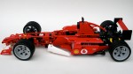
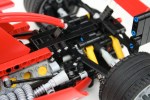
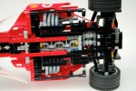
On to the rear. First to go was the trans-clear engine. Ugh. I knew I wanted to add rear suspension, but I was not sure I wanted to add a gearbox due to the limited space. I played around with some designs, and decided I should give it a go. I came up with a design that would need only 7 studs of space. The design would be off center of the car, which would present some changeover problems, but saved 3 studs of length. One axle would connect directly to the new style differential, and the other axle would connect directly to the crankshaft of the V-10. At first, I set the gearbox behind the differential, but I found that option to be rather unsightly and added some complications to the gearshift linkages. With some modifications to the chassis, moving the V-10 forward a stud, and increasing wheelbase by moving the rear axle back 1/2 stud the gearbox would fit.
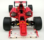
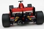
Once the gearbox was designed, I worked on the rear suspension. The gearbox got in way of the suspension design I wanted, but that was a cost I was willing to pay. I used the same upper arms as 8386, but created a liftarm design for the lower arm. Two shock absorbers connected from the chassis to the slightly modified wheel hub. While a pushrod design would have been nice, this setup worked well enough for me. I added a simple linkage to the gearbox that connected to levers in the cockpit. It looks a little clunky, but it allow all the controls to be at hand. I then made some modifications to the exhaust system so it would fit the added features. I made some modifications to the body work to give the car some visual lines that matched F2004, and added a little more white. The car was done.
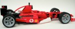
End of the V-10, beginning of the cramped transaxle.
All in all the design worked well, and required less time than some of my more fancy builds. It was a restful project, and one to which I enjoyed returning.
Maybe in another ten years, I’ll update this again with new features made possible with 10 years of LEGO changes and developments. I look forward to it.
Happy Building.
End of the V-10, beginning of the cramped transaxle.
The Kenworth T55 is my favorite Trial Truck I have built. It’s not the best looking, or the most capable, or the most reliable, or even the most popular but it’s the one I keep coming back to. My latest truck is a continuation of the Kenworth series of trial trucks. The T55 would pull a stump, the T47 is quicker, has better steering, and more compliant suspension.
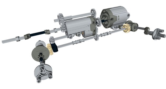
Right from the beginning I knew the truck would have a similar cabin at the T55. It would continue with the four wheel steering, and I added an independent suspension. The dimensions would stay close to the same. From there anything else was fair game. I started with the axles. The new suspensions arms made it a little bit easier to make a good independent design. A CV joint was used at the steering knuckle, which allowed for the steering pivot to be near the wheel. Each wheel had about three studs of travel.
The XL motor was placed on the left of the center line and the rechargeable battery box was placed on the right. A newly acquired Servo Motor was placed rear on the centerline directly in front of the rear axle. I had a little more space left, so I added a simple two speed gearbox. A little more space remained so I added a flat six engine.
Part of my attraction of the T55 has been it’s coloring, and it’s shape. I wanted to keep the attraction similar, but in a way that would differentiate the trucks. I have been acquiring some green lately, so I thought would be a great color. The cab is basically the same, but now it can tilt so you can work on the engine.
The off road performance was not great on the T55, and the T47 was similar. The independent suspension had too much play at the wheels to be great at steering, and the articulation was not very supple. The truck was great to drive around my house, but when I took it outside it did poorly. The suspension design is better than my last independent set up. There was no slipping of the gears. I think my next design will use the same knuckle, but design a different steering connection. This truck again proves the use of knob wheels rather than a differential for a trial truck. Feel free to make your own, and let me know what improvements you developed.