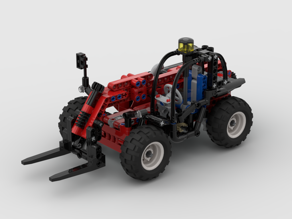
Compact Telehandler


Sometimes I plan out a build, and other times, a build just kind of happens. This was the latter.

You may find free instructions for this MOC at Rebrickable.com.

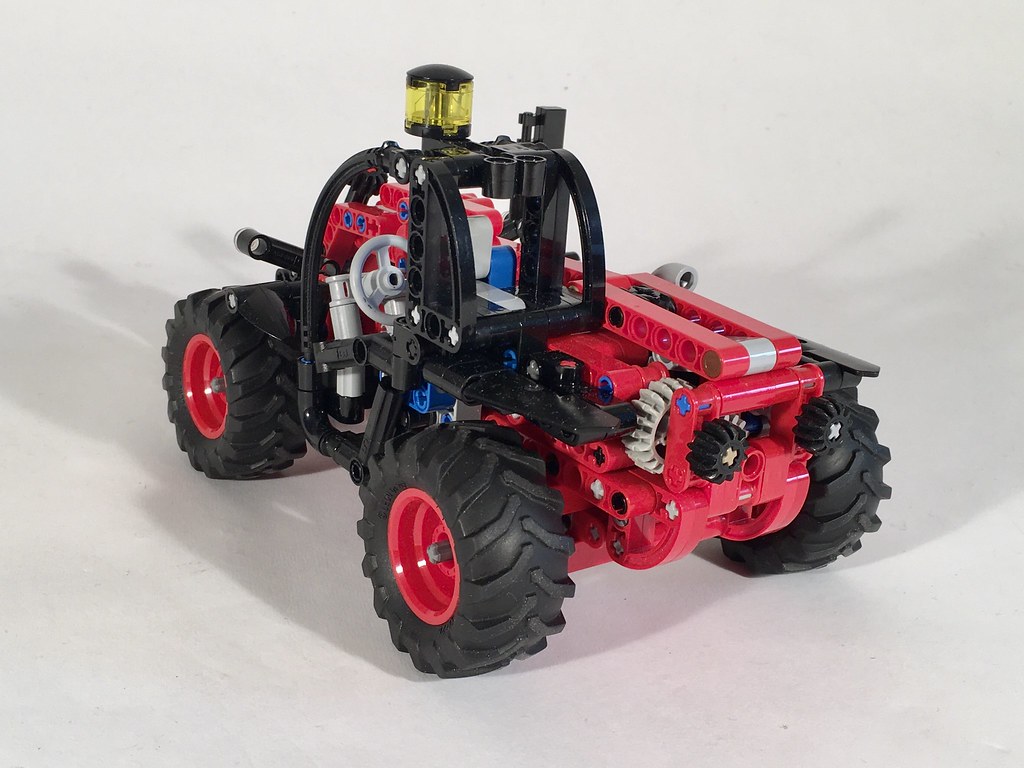
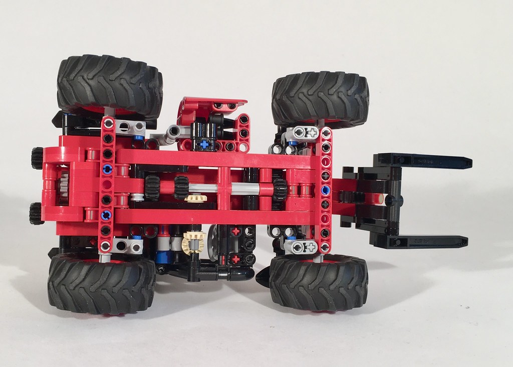
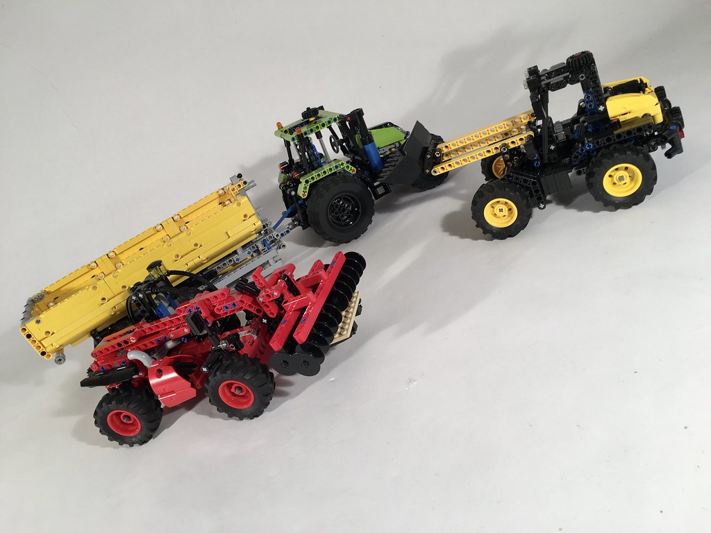
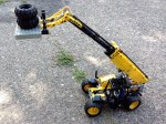
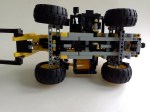
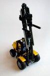
After building the Atmos Tractor, and then a gazillon implements, attachments, and trailers, I started branching out to other machines that could be used at the Thirdwigg Farm. The Compact Loader was a result of this. I was playing with the new LEGO 42122 tires, and quickly came up with a little four wheel steering idea. I added a fork boom, and decided to see where the project would go.

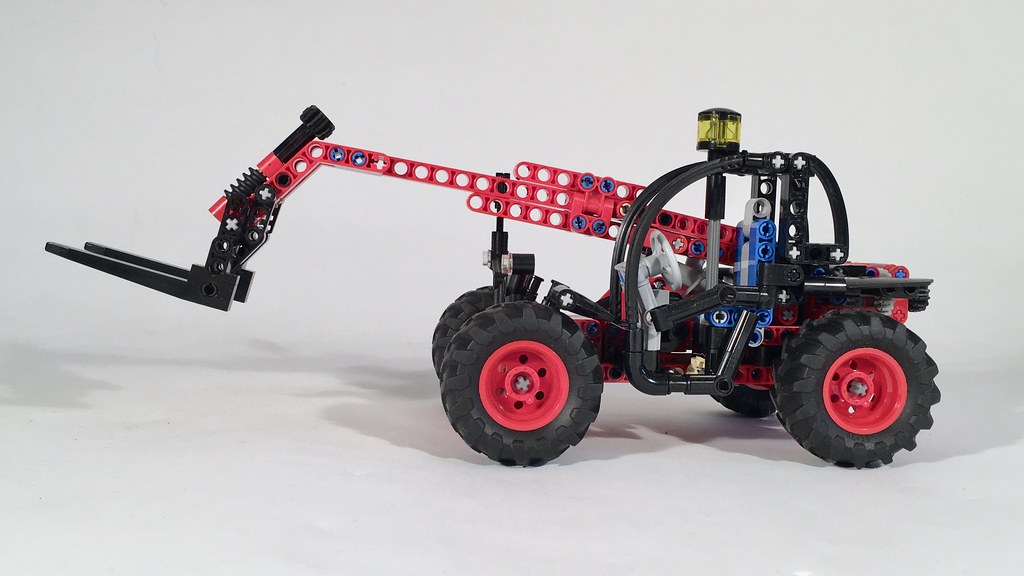
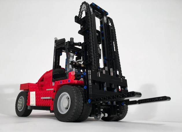
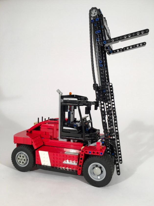
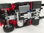
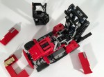
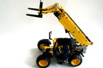
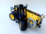
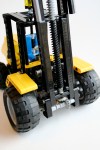
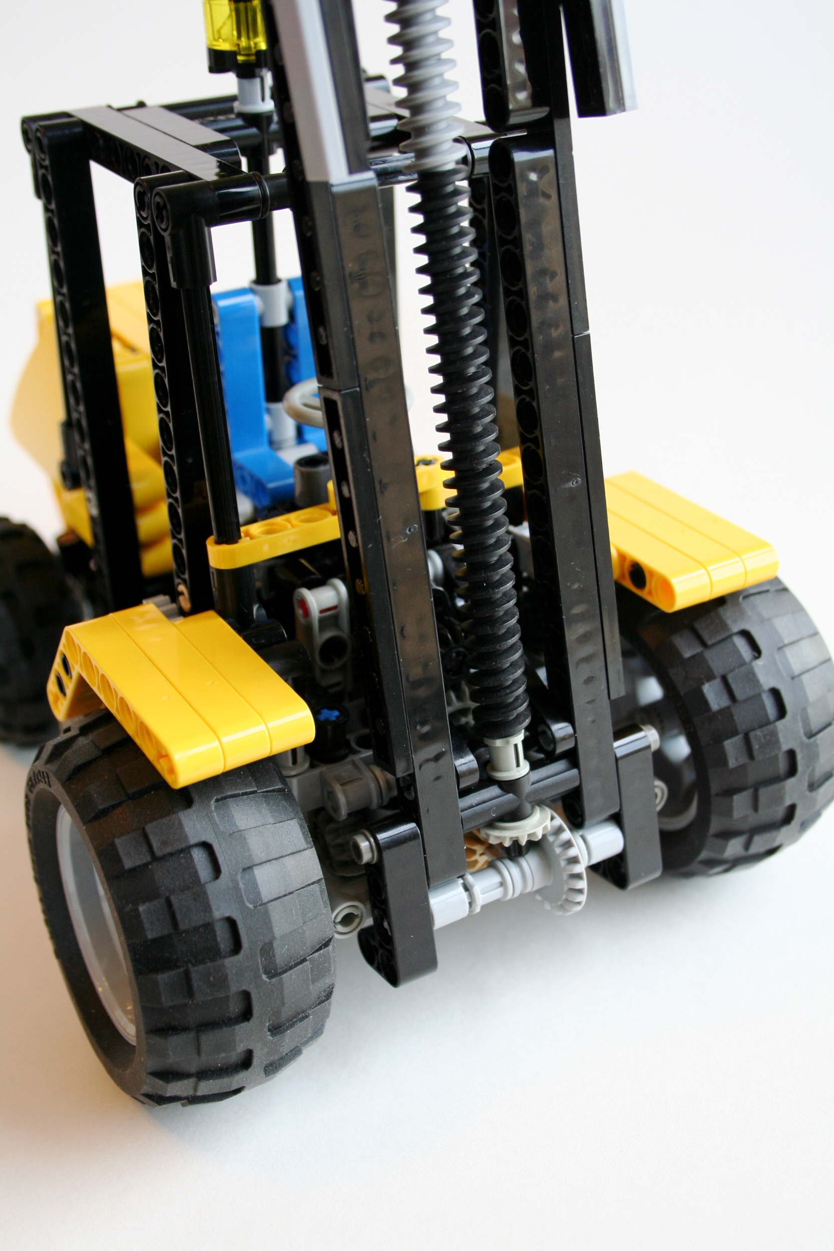
I am quite fond of LEGO 8283, and the rest of the design was influenced by this little set. I tried a couple of boom extension designs, but each looked a little too “overweight” for the little tractor. So I came back to the extension design that was used on 8283. A mini linear actuator is used to lift the boom. Both functions are controlled by two separate gears on the back of the telehandler.

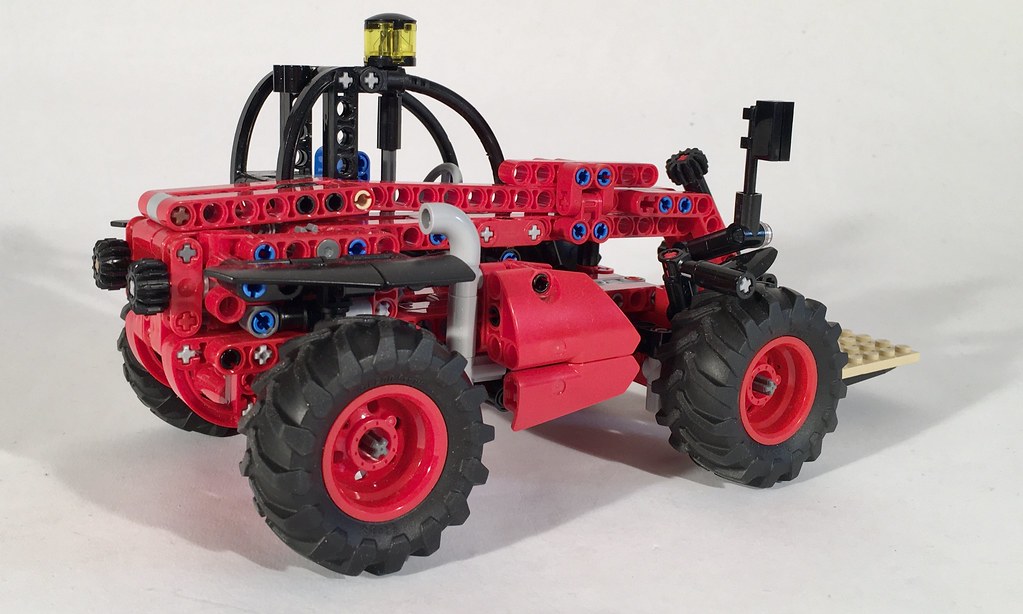
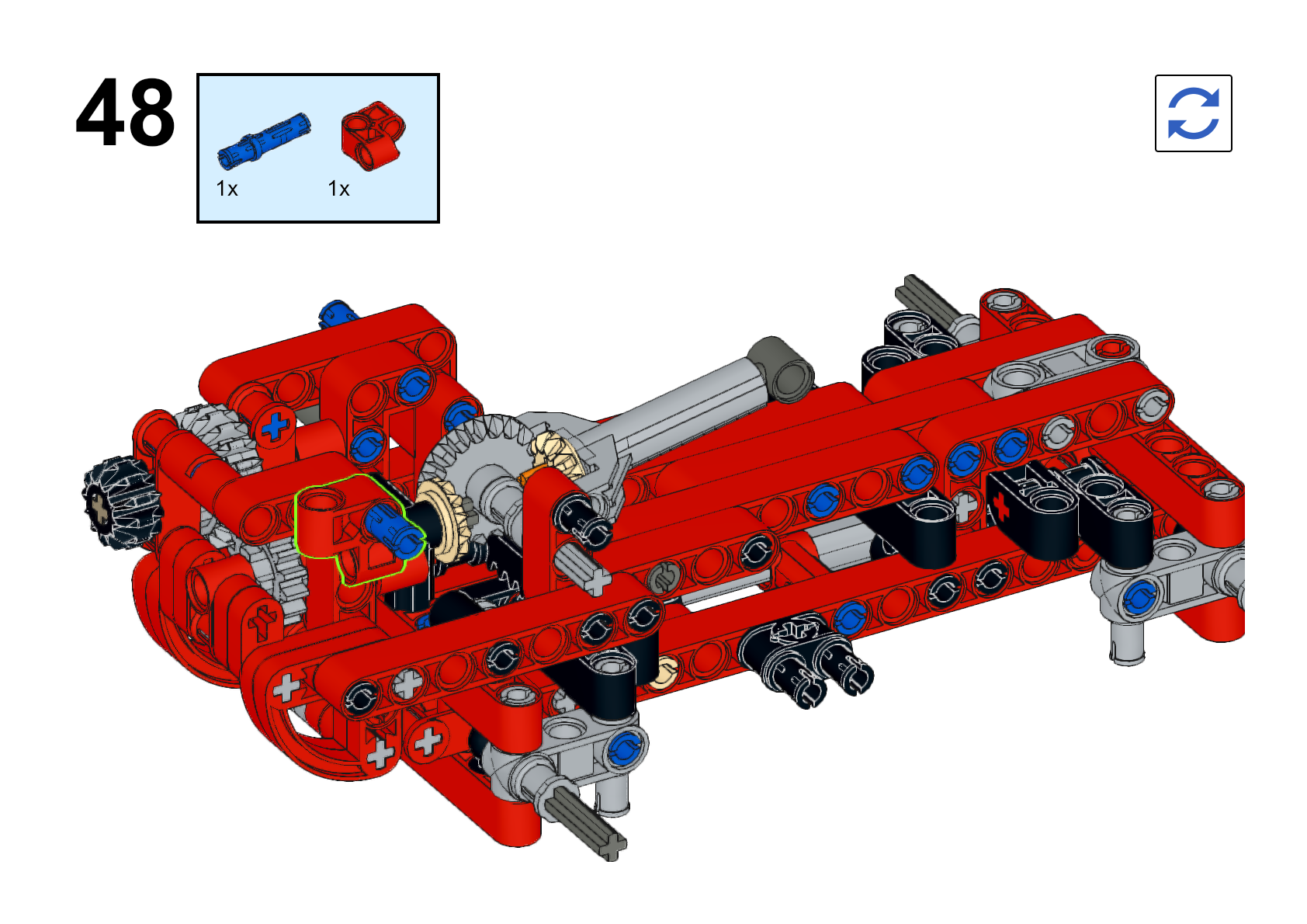
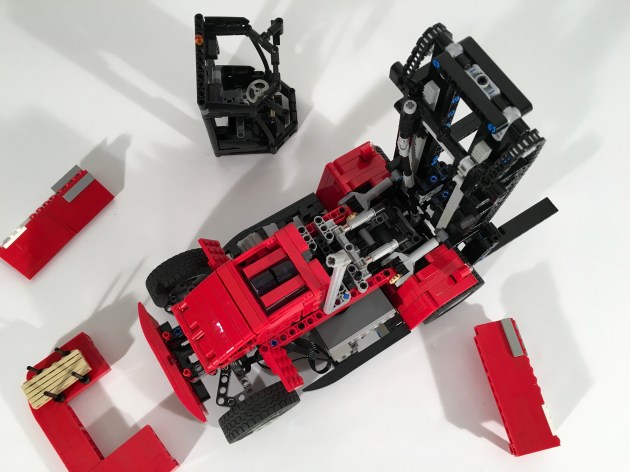
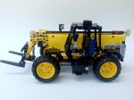
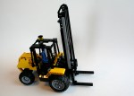
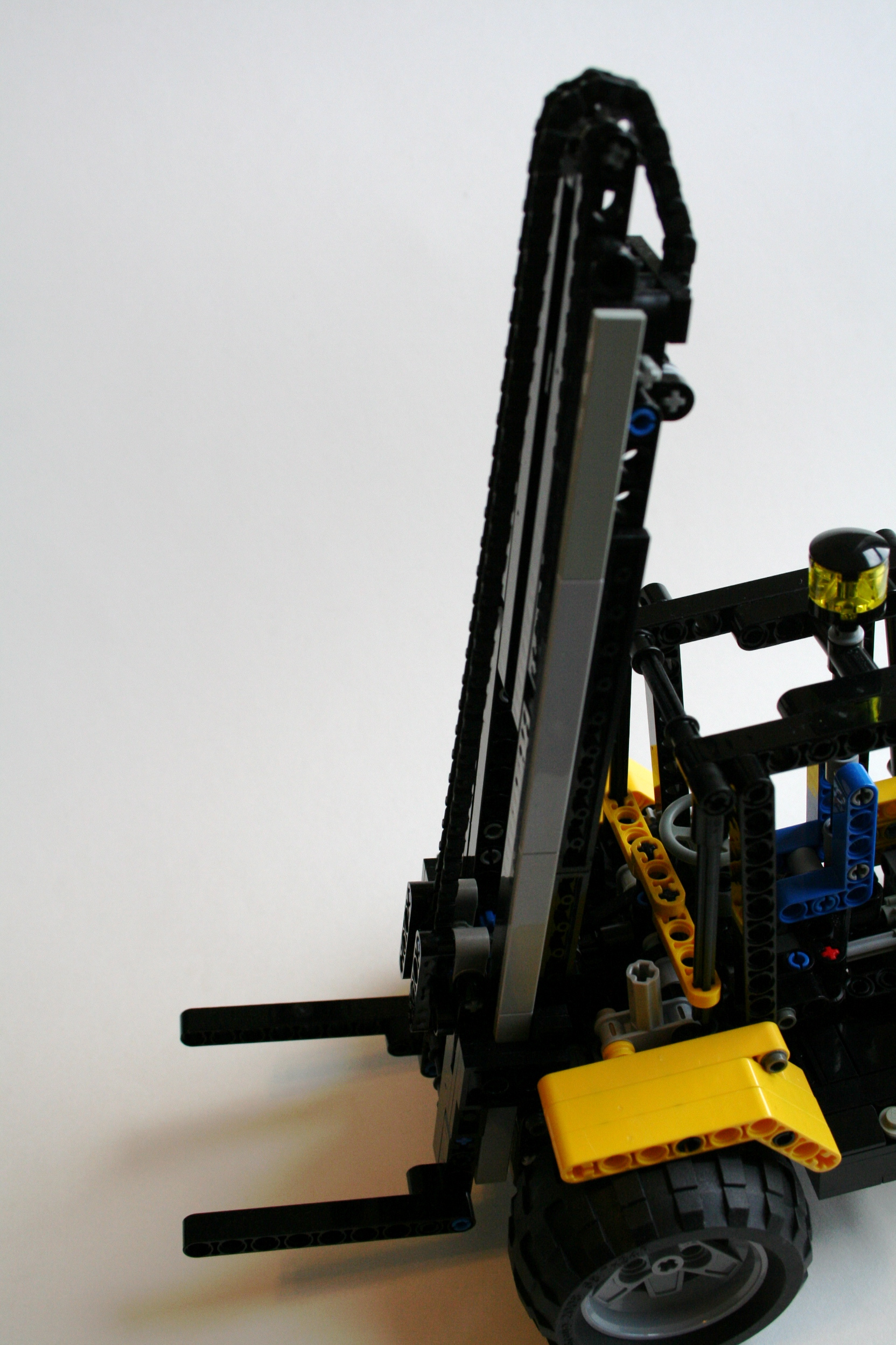
The cab came together pretty quickly, though I had to make sure the new tires had a clear range of motion. I added some lights, and front fenders which brought a little visual weight to the front. I had a tricky time finding rear fenders that I liked, but I eventually found a solution I liked. In my move towards increasing the readability of my instructions, I have published a PDF with step-by-step instructions that list required parts for each step. I hope they are clear for you, and they bring value to your own build.

The Compact Telehandler worked just as I hoped. The steering is great; it’s fun to drive this little tractor around on a small desk. The boom lift works well, and has a great range of motion. The extension works smoothly, though since it is driven by a worm gear, if the extension is in the wrong position while trying to lift the boom, the boom will bind. The fork tilt mechanism is smooth, and is easily accessible in all boom positions. We will see what next build come from just playing with a couple of parts.

Happy building.

Advertisement

Kalmar DCG180-9


After doing a lot of non powered builds, it was time for me to do something motorized. I very much enjoyed doing a forklift a couple of years ago, so it was time for another one.

See the full gallery on Flickr and Brickshelf.

Kalmar 180

The JCB930 that I did a couple of years ago was non-motorized and had some great features. I wanted to build something with all the same features, and since I would need more room for all the electronics, I decided early to model the forklift after the Kalmar mid-sized 180 model. The model would have drive, steering, a two stage lift, and fork tilt. I did not realize how hard this would be. I wanted to keep the  boom clear for visibility, and the forks not more than two studs in front of the wheels to keep integrity of scale.

Kalmar 180 Front

I set the scale and I went to work. After setting the chassis measurements, I went to work on the fork and boom. I knew I wanted to have a two stage boom, and I wanted to keep as much of the boom open as I could. The forks connect through the middle of both the first and second stage booms, and pinch both together. The middle boom is has a gear rack on both sides to lift the forks. This boom has two gears at the top, to route the chain over the top to move the forks. The outer boom is connected to the chassis at the bottom, and two mLA connect to it operate the tilt. After some working, I was able to get the boom to be thin, and just how I wanted.

Kalmar 180 Up

I decided early that I want to keep the motors out of the boom. So I had to route the lifting function out to the forklift body through the bottom pivot. This required routing the lifting axle under the drive differential. The lifting axle then move rearward, and connected up to a PF L motor. On top of the lifting axle was the drive axle. The PF XL motors was mounted transversally on the right side, and drove and axle forward to connect directly to the differential. To give me some additional space at the front, a portal axle was mounted on its side to move the differential rearward. A PF Servo was mounted in the rear, over the steering axle, and drove the steering function. The steering uses some 2×4 liftarms mounted at an angle to allow for a better steering angle. Finally, a PF M was mounted in front of the Servo, under the cabin to drive the tilt function. None of the mechanics were difficult, but the packaging required a number of drafts.

Kalmar 180 Open

The final hurdle was the body work. I spend a lot of time early in my MOCs working on packaging placement, so I do not have many body work problems later in the build. Still, some simple SNOT work was needed on the side sills to fit about the battery box, and the XL motor. Oh, and the wires. The cab was pretty straightforward, but still took a little bit of time. Finally, I had some trouble with the rear engine cover and counterweight. In the end it was a simple design that I settled on, but I tried many designs. Again, this took a lot of time.

It took a long time, but I am pleased with the final product. The functions worked smoothly and consistently. The control that was afforded by the fork functions was great. It could lift three AA battery boxes at a time. The steering was quick, and had a great lock which gave great maneuverability. The XL motor provided adequate power, and moved the forklift well. Finally, the bodywork represented the original Kalmar well. I hope you enjoyed as well.

Until next time, Happy Building.

JCB 531


Astute readers will note the heading of Thirdwigg.com has changed to read “LEGO Technic from Grand Rapids.” A slight heading change notes a rather large life change for myself, Mrs. Thirdwigg, and Jr. Thirdwigg. This has caused a slight hiccup to production and the timeline of The Queue, but we are back in business.

A working telehandler has been on my list of machines to build for a long time. I finally acquired a 32l axle, and it was the impetus I needed to start the project.

The full gallery is here.

Ready to take on any project.

Ready to take on any project.

Right from the beginning I decided the MOC would have steering, boom lift, boom tilt, and boom extension. All the functions would be manual as is my current trent (do not fear, it will be over soon), and would be housed within the boom itself. I based the scale for the MOC on the length of the boom being 32 studs so I could use the full 32l axle.

The 32l axle was placed on the top of the boom, and would allow the sliding 8z gear to transmit rotation to the fork tilt throughout the full extension of the boom. At the end of the boom I added a mLA to adjust the tilt of the fork. It took a little working, but I eventually figured out how to adjust the tilt for every position in the lift. I then worked on the boom and the extension so it would be as stiff as possible through all points of the lift.

I then worked on the chassis and the cab. The chassis was rather basic, and after a couple of rebuilds to get the steering right, it was done. I did have to do some revisions to have the boom/chassis interface more rigid. It turns out that when the boom was fully extended, the lift would sway a little too much. I then added a cab and the engine box on the right side. Here you can see the final project working.

The MOC worked well, and other than a slight sagging of the boom at full extension, I would not change a thing.

Happy Building.

JCB 930 Forklift


It was time for me to to make something that was a little smaller with a lot of functions.  I kept driving by a JCB forklift on the way to work, and I thought I could make that.  I wanted manual functions, including a working fork tilt and dual stage lift, working steering and drive, and a yellow bodywork.

I always start with the hardest part of a model.  For this model, that was the fork.  I wanted to use a dual stage lift as to get the forks to a substantial height.  This design would require a chain that would wrap over a moving frame, and connect on one side to the forks, and on the other side to the body.  The moving frame would be moved by a screw, thereby lifting the forks.  I used a number of worm gears on two 12l axles, connected through the bottom to move the moving frame.  This setup allowed for a pivot point, and a lifting mecanism that would function much like the real JCB 930.  The moving frame consisted of two rows of liftarms, and the forks tied everything together between the moving frame and the worm gears.  A chain went up and over the full assembly to work move the forks as the moving frame was lifted.  It works like this.

I then worked on the driveline.  I added a 3 cylinder motor in the rear, driven by the front wheels, working to keep the functions out of the way of the fork mechanism.  I added a steering axle on the rear, and gave it a pendular suspension setup.  This allowed for some stability on uneven ground, while keeping the front wheels planted for the load as it had no suspension.

I then built the body after the JCB 930, and as I did, I added a tilt freature to the fork.  This feature did not work too well, but it gave me the ability to adjust the pitch of the forks, which we a design requirement.  It was not too stable.  After a little work to the body, and a HOG steering link out the top of the cab, the model was done.

The model worked well, particularly the lift feature.  I was a little disappointed with the tilt feature, as it was a little too wobbly. The drivetrain worked well, and the steering allowed for tight corners.  The suspension give good stability, and offered a little bit of off-road prowess.

The full gallery is here.