There are not many projects I start that I do not finish. I can count a couple. But, sometimes there are projects that take a long time to complete. I either loose motivation, lack parts (read budget), or find something else to do. If I were wise, I would toss the project, and move on to something better. But there is value to trudging through the slog and completing something difficult. The Spitfire is a great example of this. The Audi Allroad has been on The Queue for about 16 months, and it’s finally done.
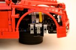
After completing the OCTAN F1, I thought I could use the suspension for an all-wheel drive car. I was sure I could make the front suspension with steering work at this scale.
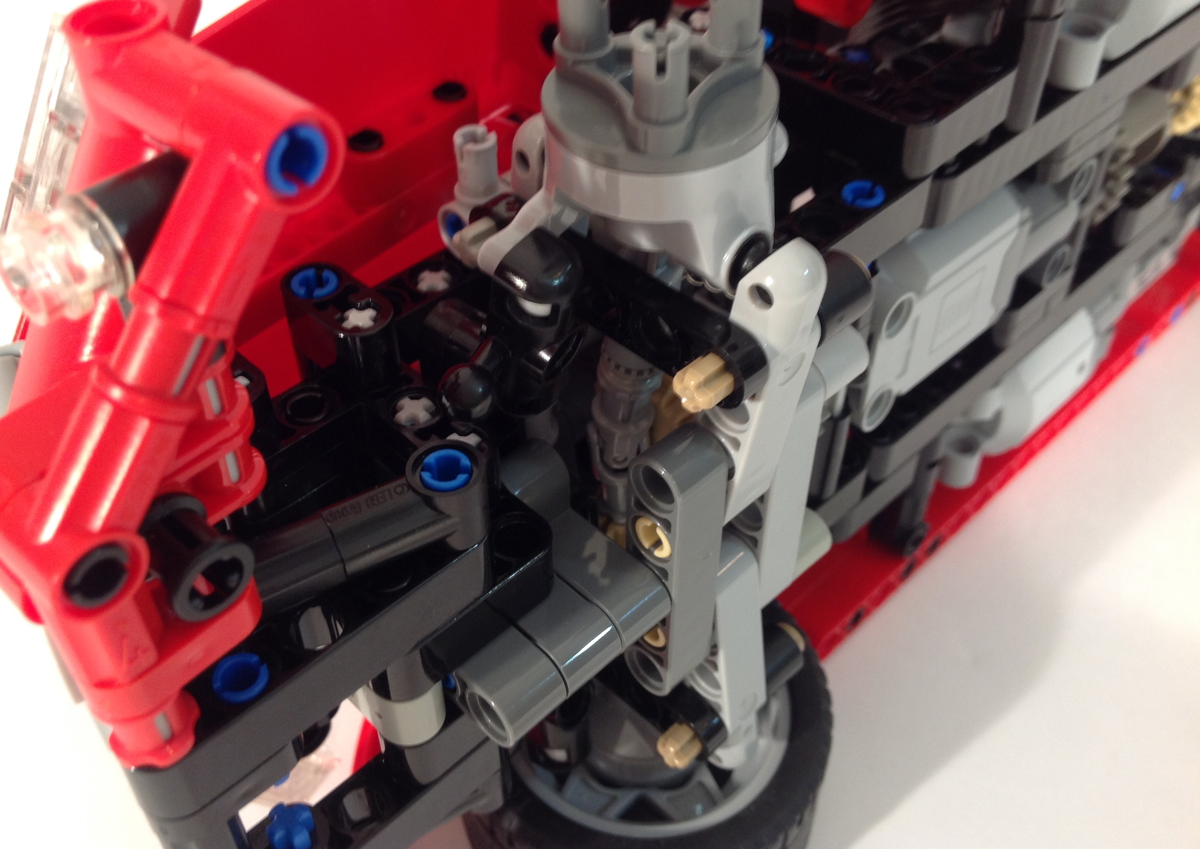
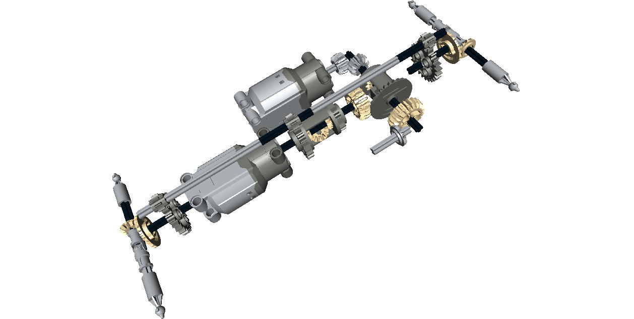
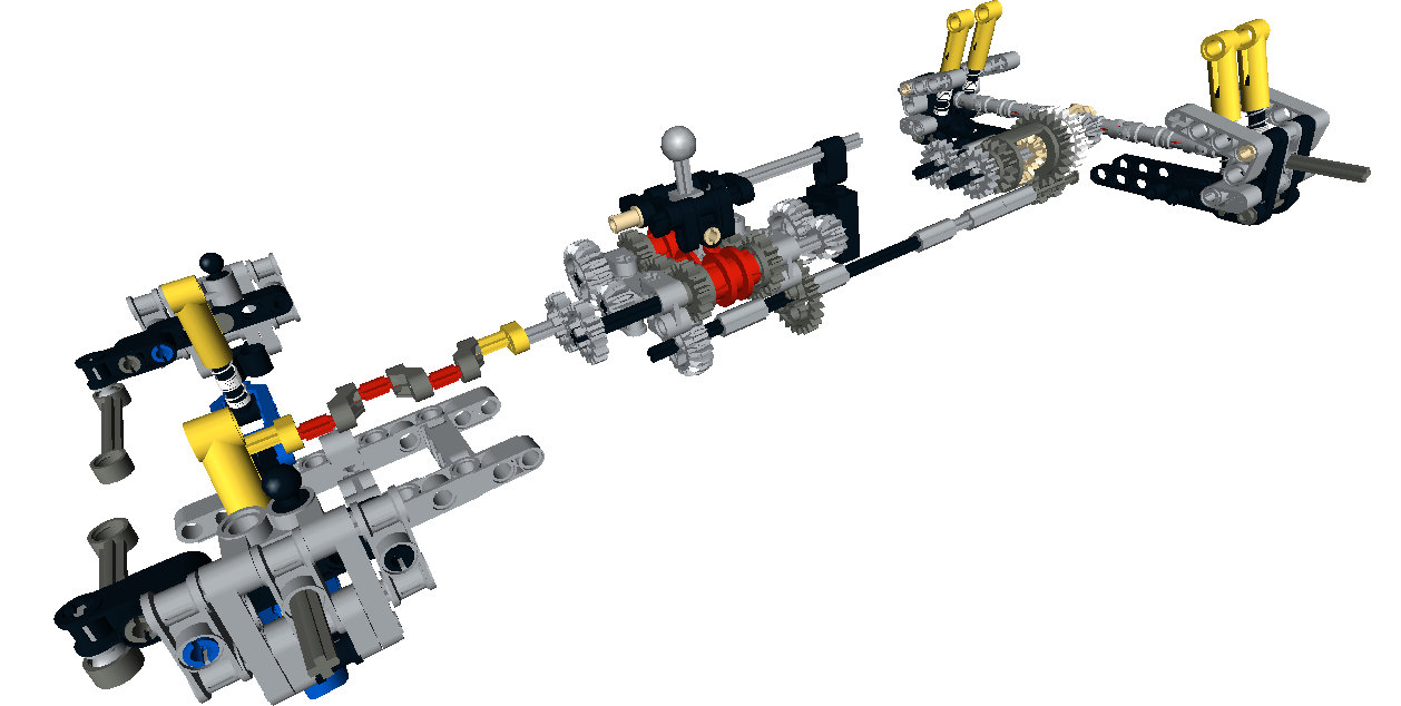
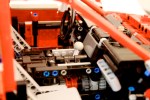
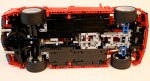
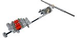
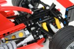
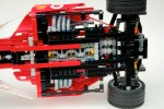
I wanted it to have another fun feature, so using a bunch of differentials, I developed a simple three speed transmission. Three power functions motors are connected via two differentials which connect to the drive axles. Each differential acts as a subtractor between each motor. When one motor is running, the power moves through two differentials, and the car moves slowly. When two motors are running, the power moves through one differential, and it’s a little faster, and when all three motors are running the car is running the fastest as no differentials are splitting the power. I got it to work, and within a day, I had a working chassis.
Once this was done, the MOC sat on my desk for a long time. This past fall, Thirdwiggville welcomed another citizen to the village, and this gave me lots of time late at night to get back to working on this project. I spent a couple of weeks working on the body work with the perspective of “finish this.” So the body work could use a little more polishing; doors, mirrors, better lines, maybe an interior. But I was happy to finally get this done.
The MOC worked well. The suspension functions quite well at this scale, and the transmission was simple and effective. It could be a little quicker, but I was not going to make a substantial gearing change after the MOC was built.
Two final thoughts. I need to stop building supercars because they take a lot of time and effort for me, and I find little motivation for the body work; I do not think the body work looks good, and I lack motivation to work on it. Second, I needed to test the driveline earlier in the build process. I spend too much time fiddling with gear ratios after everything was build. But this project is done, and I am happy it is.
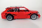
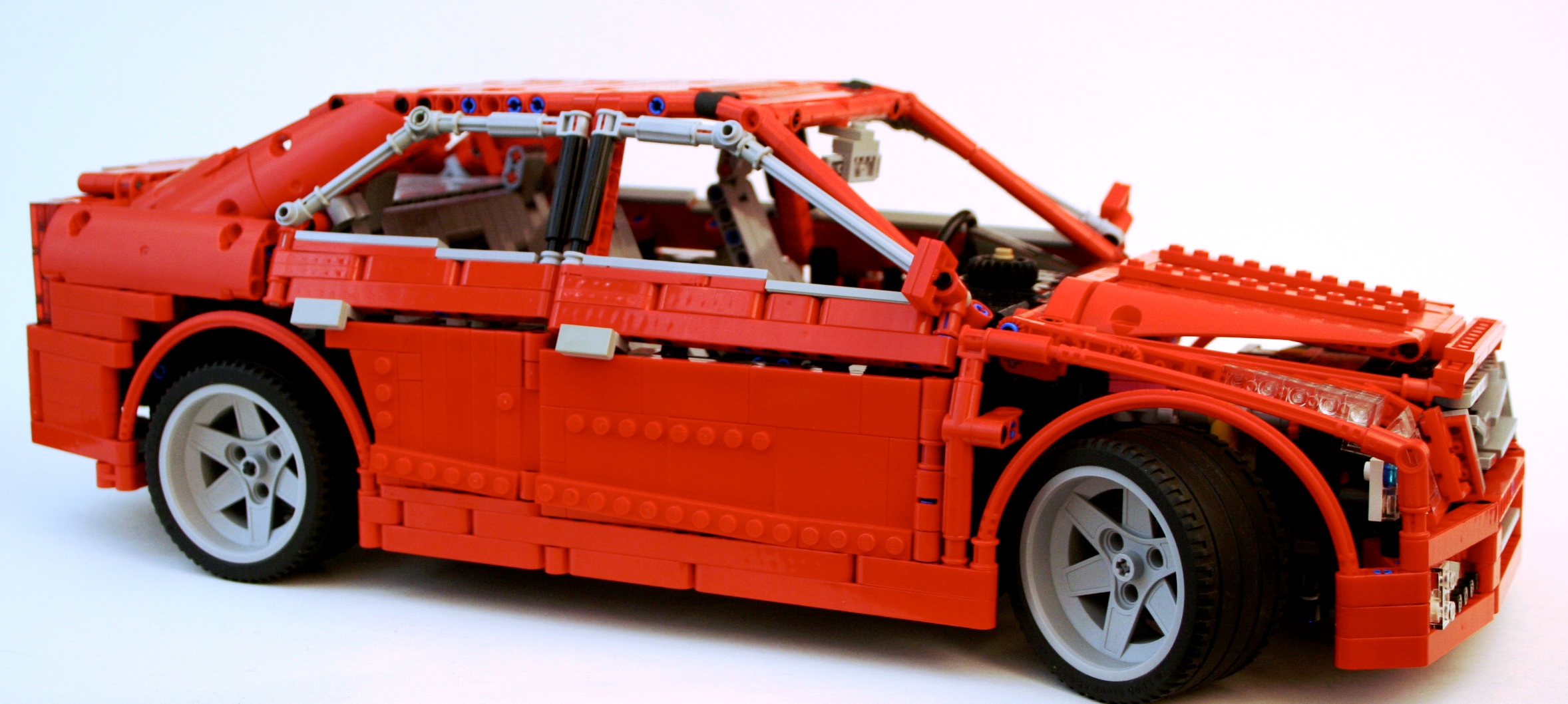
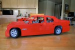
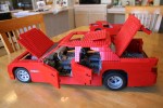
A while ago I decided I was going to do a proper new school supercar. Something with all the features that are to be expected in the LEGO Technic Community. You know what they are; suspension, a gearbox, opening doors, a working engine, steering, and something fast looking. Probably red. It was time to test my chops and throw my hat into the ring.
The full gallery can be viewed here, and instructions may be purchased for $9 USD. Partlist
It has been a long time since I have built a supercar. While I enjoy many of the cars others make, I long for exceptional creativity in suspension design, gearboxes, and body style. It was time for me to build another one and contribute to these areas. About two years ago I set out to create a six speed gearbox that would have a more realistic gear change movement. I tried linkages, springs, and so many gears. In a bit of a breakthrough, I offset the two outside changeovers vertically by 1/2 stud. This allowed for the changeover lever to connect all three changeovers as it rotated from a single center pivot point. Once this design was completed, it needed a home.
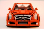
I have a preference for sedans rather than coupes. Plus too many two-door supercars have been created. Forgive the slight nationalism, but I thought it would be fun to do an American sports sedan, so a Cadillac was the best choice since the demise of my beloved Lincoln LS. The ATS was new, and at the scale would be a little more manageable than the CTS. I worked a little on the scale of the car. Some parts would be a challenge to convey the look, but I was ready to start building.
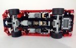
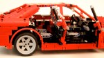
I started with the front suspension. The new suspension arms allowed for a short/long arm setup. The two different arm designs allowed for a increasing negative camber as the suspension moved through its travel. Additionally, the pivot points on the steering hub allowed for a kingpin inclination to provide an improved caster angle. Finally, I added Ackerman geometry to the steering link. After some work mounting the suspension, and the rack and pinon steering, I had the front suspension done.
The rear suspension was more simple, but still had some unique features. While the real ATS uses a 5 link setup in the rear, I was not too impressed with the results I came up with as too much flex was found at the wheel. I started with a transversely mounted limited slip differential that I have used before. This connected directly to the two half-shafts for the rear wheels. I applied a short/long arm setup for the rear suspension so the tires would keep their contact patch as the body would roll through a corner. Like the front, this created increasing negative camber as the suspension moved through its travel. Normal in real cars, not often replicated in LEGO.
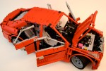
Tying all of these parts together was a little bit of a challenge. I wanted the steering wheel to be connected to the steering as well as a HOG knob on the dashboard. In addition, the doors, trunk, and hood should all open. Naturally, the car had to have a spare tire, and various engine options which could be easily removed. The chassis had to be stiff enough for the suspension to function well. Packing this all together took some time. About 9 months, but who is counting?
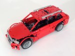
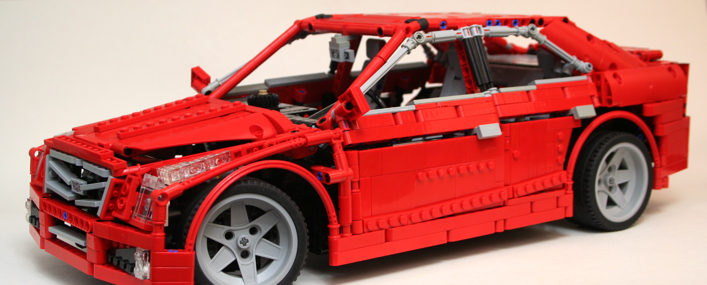
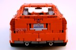
But what took the most time was the body work. This is the part for which I have little motivation, and the important part that would identify the car as an ATS. I had a lot of work to do. And my palmares have not trained me well for this task. After major parts were placed, and the dimension were set (37 stud Wheelbase, 60 stud Length, 25 stud Width), I worked on one section at a time. As the front bumper was part of the chassis, this part was developed early. As did the rear bumper. The headlights are unique for the ATS, so this was done early as well. After the roof was placed I worked on the trunk, which came together rather easily. I worked on the hood of the car, and after two designs I was happy with the result. I then worked on the grill, and after tinkering with a couple of SNOT techniques, I was able to get most of the distinctive Cadillac grill in my design.
Then off to the doors. I made seven designs. Most sedans these days have various creases that identify their sedan as different than any other sedan. You will notice the ATS has two, one on the bottom that rises slowly to the rear, and one midway up to the windows that moves along the length of the car from the hood to the trunk. The top line was accomplished by having the angle for the windows start a little lower on the front door and higher by a 1/2 stud on the rear door. The bottom crease was added by attaching some angled plates to the bottom of both doors, which cant slightly inward. Finally, both doors have an upper pivot point that is 1/2 stud inboard to bring the upper part of the doors toward the center of the car. Once I got a design I liked, I had to bring it all together to make sure everything fit well. I adjusted the roof, modified the hood, tightened up the dashboard connection to the doors, and made some changes to the rear quarter panels. There were still some areas where improvement could be made, but I was running out of ideas. I was pleased with the result. Pleased enough to say I was done.
All in all, I was pleased with the result of the car. As this is my first studless supercar, I was happy with how it turned out. The functions were up to my standards, and nothing was compromised as the car came together. While I was overwhelmed with the bodywork, I was pleased with how it turned out. Because it took me a long time to get it to work, it may be a long time before I do another one. I was happy I did a sedan, and hopefully a new moniker can begin in the LEGO community. #supersedan.
On December 18th, 2004 I bought 8386 here in Cologne, Germany. It was the first LEGO set I bought in 7 years, and thus was the end of my Dark Ages. It was my return to LEGO. Today marks ten years since I bought this set. This is a celebration of that event 10 years ago.
A lot has happened in the last ten years. When I think about that time I pause to reflect on where I have come. I have lived in 10 different places, including three states, had a number of different jobs, and increased my family unit by a factor of three. But people don’t come to this website to read about me, they come for LEGO. Over the last ten years we have gained much. The Technic line has improved both in terms of functional abilities, but also in the frequency and quantity of models offered. We have gained Power Functions. We have Linear Actuators, CV joints, more suspension parts, and so many more wheel options. We have favorite elements that did not exist ten years ago. Colors now include green, blue, white, and orange. LEGO made a Unimog. Bricklink started not much more than 10 years ago. Let that sink in for a moment. All of these developments have made so much of my building possible. It only makes sense to celebrate with a MOD of the set that reminds me of my return.
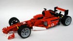
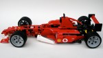
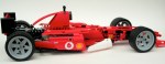
8386 was a rather basic set. It was modeled after the F2004 car #1 or #2 of the 2004 Scuderia Ferrari team through a licensing agreement with Ferrari. The cars were rather successful during the 2004 season at the hands Michael Schumacher and Rubens Barrichello. 8386 included working steering, a working V-10, and a removable engine cover. And that’s about it. Oh, and a lot of stickers. As I did with the 8081 4×4 my goal was to keep what was there, and improve what I could. I would add some additional features, namely suspension and a gearbox. Since 2004, LEGO has added a number of elements that made these goals easier than they would have been ten years ago.
First, I built 8386 as is. After a good hour, I had the stock 8386 complete. I had my constraints, so now I needed to modify the set. I started with the front suspension, as I thought that would be rather difficult. Turns out it wasn’t. I removed a couple of axles, and added in two hard shock absorbers. The geometry made the suspension adequate. It could have been a little harder, and could have been a little more aesthetically pleasing, but it worked.
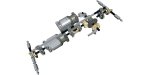
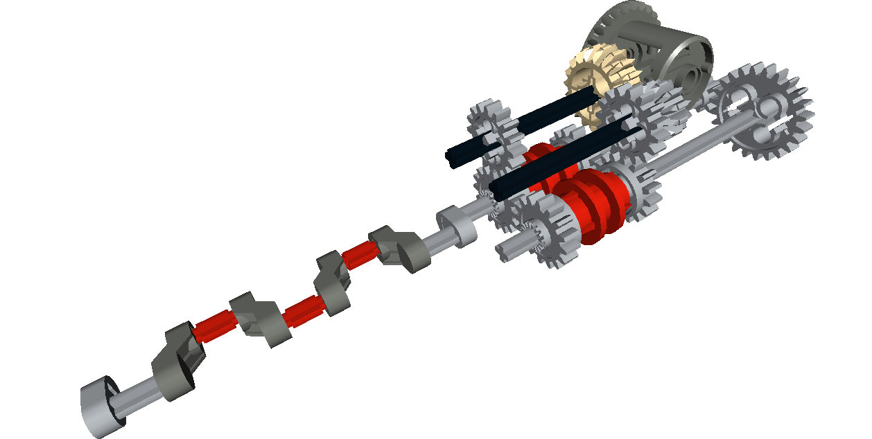
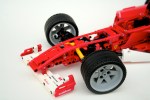
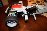
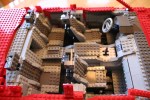
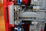
On to the rear. First to go was the trans-clear engine. Ugh. I knew I wanted to add rear suspension, but I was not sure I wanted to add a gearbox due to the limited space. I played around with some designs, and decided I should give it a go. I came up with a design that would need only 7 studs of space. The design would be off center of the car, which would present some changeover problems, but saved 3 studs of length. One axle would connect directly to the new style differential, and the other axle would connect directly to the crankshaft of the V-10. At first, I set the gearbox behind the differential, but I found that option to be rather unsightly and added some complications to the gearshift linkages. With some modifications to the chassis, moving the V-10 forward a stud, and increasing wheelbase by moving the rear axle back 1/2 stud the gearbox would fit.
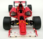
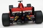
Once the gearbox was designed, I worked on the rear suspension. The gearbox got in way of the suspension design I wanted, but that was a cost I was willing to pay. I used the same upper arms as 8386, but created a liftarm design for the lower arm. Two shock absorbers connected from the chassis to the slightly modified wheel hub. While a pushrod design would have been nice, this setup worked well enough for me. I added a simple linkage to the gearbox that connected to levers in the cockpit. It looks a little clunky, but it allow all the controls to be at hand. I then made some modifications to the exhaust system so it would fit the added features. I made some modifications to the body work to give the car some visual lines that matched F2004, and added a little more white. The car was done.
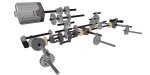
End of the V-10, beginning of the cramped transaxle.
All in all the design worked well, and required less time than some of my more fancy builds. It was a restful project, and one to which I enjoyed returning.
Maybe in another ten years, I’ll update this again with new features made possible with 10 years of LEGO changes and developments. I look forward to it.
Happy Building.
End of the V-10, beginning of the cramped transaxle.
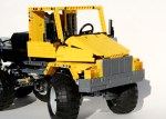
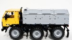
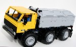
The Kenworth T55 is my favorite Trial Truck I have built. It’s not the best looking, or the most capable, or the most reliable, or even the most popular but it’s the one I keep coming back to. My latest truck is a continuation of the Kenworth series of trial trucks. The T55 would pull a stump, the T47 is quicker, has better steering, and more compliant suspension.
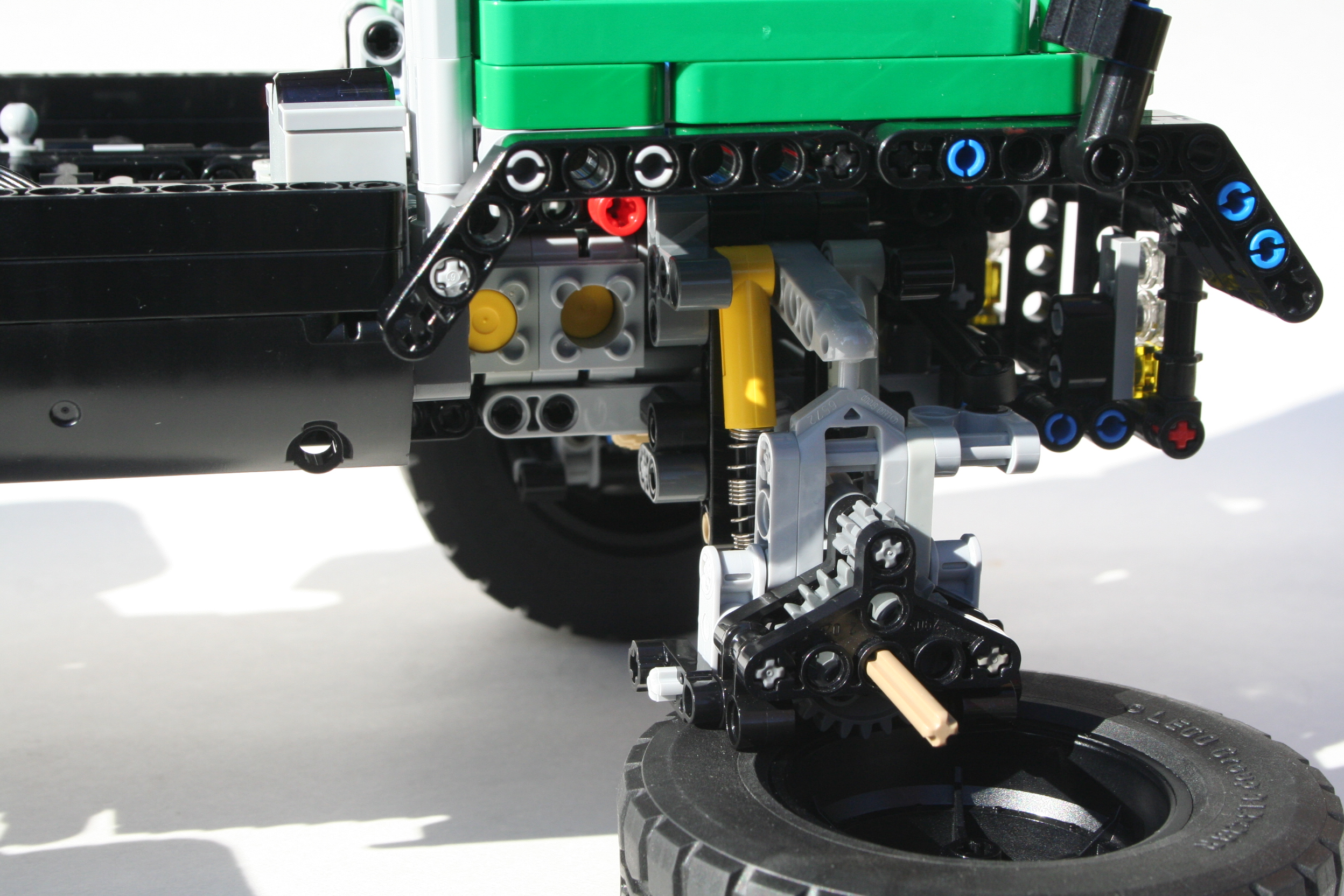
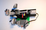
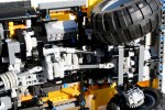
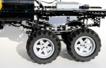
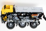
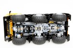
Right from the beginning I knew the truck would have a similar cabin at the T55. It would continue with the four wheel steering, and I added an independent suspension. The dimensions would stay close to the same. From there anything else was fair game. I started with the axles. The new suspensions arms made it a little bit easier to make a good independent design. A CV joint was used at the steering knuckle, which allowed for the steering pivot to be near the wheel. Each wheel had about three studs of travel.
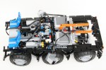
The XL motor was placed on the left of the center line and the rechargeable battery box was placed on the right. A newly acquired Servo Motor was placed rear on the centerline directly in front of the rear axle. I had a little more space left, so I added a simple two speed gearbox. A little more space remained so I added a flat six engine.
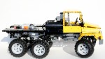
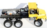
Part of my attraction of the T55 has been it’s coloring, and it’s shape. I wanted to keep the attraction similar, but in a way that would differentiate the trucks. I have been acquiring some green lately, so I thought would be a great color. The cab is basically the same, but now it can tilt so you can work on the engine.
The off road performance was not great on the T55, and the T47 was similar. The independent suspension had too much play at the wheels to be great at steering, and the articulation was not very supple. The truck was great to drive around my house, but when I took it outside it did poorly. The suspension design is better than my last independent set up. There was no slipping of the gears. I think my next design will use the same knuckle, but design a different steering connection. This truck again proves the use of knob wheels rather than a differential for a trial truck. Feel free to make your own, and let me know what improvements you developed.
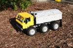
I have said it before, but my favorite things to build are Trial Trucks. The combination of the driveline construction, forces on the truck, diversity of body style, and various propulsion systems offered by LEGO combine for a great building experience. Because of this, I usually am building a Trial Truck, or have one built at all times. But for some reason, this truck seemed to sit for a long time unfinished. I struggle with deciding if a truck will be a model of something, or something fictional. This decision is often made too late in the construction process. After toying with a Daimler Scout body, I decided I needed to finish this project and the Bedford MWD body was chosen.
After some some experience with various designs, I decided to construct a truck around a simple locking differential idea I had recently designed. Because I would need an extra IR Receiver for the locking function, I decided a simple two speed gearbox (1:6 and 1:10) could use the other IR channel. I placed all the controls in the middle of the chassis. The driveline and the steering axle would run through the middle. On the left side was the Battery Box and the motor for the gear change, and on the right side was the XL drive motor, the gear box, and the motor for the locking differential mechanism. The steering motor would hang out the back of the chassis over the rear pendular suspension unit. Both axle were connected by my favorite linked suspension system.
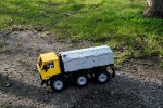
Each axle took a little bit of work. I selected a simple design for the locking differential. Basically, it is a 24 tooth differential placed directly next to a 24 tooth gear. A pair of sliding 12 tooth double bevel gears slide back and forth one stud to connect only with the differential, or with both the differential and the neighboring gear locking out the differential. After toying with some old flex cable, and some pneumatics, I figured I was making it too complicated. I added a small pivot with a Small Technic Steering Arm, and connected it to a 9L link. This way both axles could be connected, the suspension and lock could keep operating unaffected by each other, and it all could be controlled by a mini Linear Actuator.
Initial tests were positive, so I then decided to figure out a body for the design. I worked for too long on a Daimler Scout body. I had the structure made, but the paneling was just not happening. After sitting on the project for 5 months, I decided it was time to make something new. The Bedford design worked well, and helped my get excited again in the project.
Now, once I got outside to drive the truck a glaring problem occurred. The bevel connection in each axle that transmits the longitudinal drive forces to transversal drive forces kept slipping. You can hear it in the video. Because of this, it did not matter if it had locking differentials, or if it had a two speed gearbox, or if it had working suspension. Anything could stop it. I though about reworking the axles, but then, I have been working on this for 11 months, it was time to be done. I’ll use the locking mechanism again. That worked great.
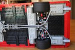
A couple of years ago, I was building a MAN LE with the sole intention of creating a new gearbox. The tried and true changeover with clutch gears is a great system, and works well in a lot of situations, but I had been disappointed with how it functioned in trucks. Particularly with the neutral. I could not have my trucks roll backward. There had to be a better system. There were four things I wanted to address:
First, each gear-change had to move seamlessly from one gear to the next. No neutral.
Second, it had to be easily controllable with power functions.
Third, it had to be sequential. No first to third gear shifts.
Fourth, it had to work. Every time. With no slipping.
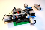
The first goal was easy to address. I came up with a simple sequential gear box, that would move between three ratios all spaced one stud apart. In order to get to gear three, you had to go through gear two. To make sure the gears would slip into sync every time, I chose the double bevel gears as the change over gears. You can see in the video how they slide into gears pretty easily.
The second goal was the most difficult. I have stuggeled with finding a solution that would allow a motor to move from one great to the next without “overshifting.” To many designs require you to stop the motor so the gears are perfectly meshed. After looking at a design from ATRX, I had an idea. I needed to use the pulley wheels to move the gearbox in three steps. So, how could I get the pulley wheels to stop at three spots around a half a rotation. The pulley wheels would be connected via a 24z gear to a differential. Each side would have M motor, with stops for half a rotation. One motor would move a half a rotation, transmit the rotation through the differential which would turn it into a quarter rotation, moving the pulley wheels a quarter rotation as well. One motor would shift from gear 1 to gear 2, then the other motor would shift from gear 2 to gear 3. It was sequential, and it would only allow you to shift to the adjacent gear.
Finally, it worked. Every time. No missed shifts. I have made a couple of modifications to the gearing and structure to make it a little more compact and with better ratios, but if your looking for a new gear box to use for your next MOC, this might be the ticket.
It has been a little quiet in Thirdwiggville for the last month. I have been working on a project that is taking a lot of time and resources, so my posts have slowed, even though my building has not. But just wait, it’s going to be awesome.
Last summer I wanted to do another Trial Truck that would utilized some features I have never used before. I wanted something complicated to see how it would work. I wanted a model that would use four wheels steering, independent suspension, and have a simple two speed gearbox while being low to the ground. After spending some time at the Chicago Autoshow, I saw a FTTS concept, so I thought this would be a great vehicle to model for this next truck.
This model would be built around an independent suspension. After seeing it used so effectively in a truck by ATRX, I wanted to give it a try. Each of the four wheels would use a simple double a-arm set-up with a wheel mount attached at the outside. The wheel mount would house the portal axle and connect the steering linkage. After a couple of different designs, I also decided the wheel mount would also connect the the shock absorbers. This was a little unorthodox, as most independent designs mount the shock absorbers directly from the frame to the a-arms. I did this for two reasons. First, the model would be heavy, and I could not get the support I needed when the shocks were connected to the a-arms. Second, and most importantly, I noticed too much suspension flex when the shocks were mounted to the a-arms. The force applied to the wheel would go up the wheel, to the wheel mount, through the pivot, halfway down the lower a-arm to the shock. LEGO is relatively stiff, but all these steps complied too much flex. I would not have it. I mounted the shocks on the wheel mount, and created a simple MacPherson strut set-up. This worked well, as it allowed for full steering movement, long suspension travel, and adequate support of the truck.
The front and rear suspension axles both had a PF-M motor driving the steering. Each were on independent PF channels connected to a single 8878 Battery Box to allow for individual steering, crab steering, and to solve steering drift commonly problematic with four wheels steering vehicles. Both axles were connected with dual drive shafts running the length of the truck. One drive shaft would then connect through a simple two speed gearbox to the PF-XL motor. The final gearing was 1:6.2 and 1:10 for the truck. This gave the truck sufficient top speed, with an effective crawler gear. The Battery Box used for the drive motor and the gear shift motor was placed directly behind the front suspension, and in front of the drive motor. This placement was perfect for stability. It helped give great traction to the front wheels, kept the center of mass low and to the center with a slight forward bias.
I then finalized the model with a simple removable body built on a Technic frame. While the hood was little high, and the rear body a little too short, it looked pretty close to the rear FTTS. Fans seems to like the look, as it is still one of my more popular model. See the full gallery here and the Work in Progress gallery here.
The model was a lot of fun to drive, and due to its squat design, it was very well planted. The truck did not want to role over. I think it could have used a little more suspension travel, and having four wheel steering was crucial to give it some maneuverability that was lost due to the suspension design. The gearbox was flawless. The truck did have some trouble skipping gears at the portal axle. It seemed to happen when a single wheel was over-stressed as the driveshaft could have used stronger bracing in each suspension unit. This placed a lot of strain on the particular wheel. So would I do the independent suspension again. Maybe, but it would need some strengthening and redesign. Maybe it’s time for another truck like this.
For some reason, I often find myself building two trial trucks at the same time. While I was building my ZIL 132, I also wanted to try something with floating axles. The model would use 6 wheels, a 3 speed transmission, and fully suspended live axles. I also wanted to model the Freightliner M2 Business Class truck as closely as I could.
The model started as my trucks usually do; with the axles. The second and third axles would be identical, and would be connected with a simple pulley wheel universal joint between the two. To keep the speed through the universal joints high, and the torque low, I used as 12z/20z gearing after the universal joints, then the knob wheels to rotate the axis, then the normal 8z/24z gearing on the portal axles to finalize the drive. This also allowed me to keep fewer knob wheels as the second axle had the drive shaft from the transmission pass uninterrupted to the rear wheels. The final drive ratio for the two rear axles were 1:5.
The front axle was a little more work. I wanted to have the steering motor mounted on the axle so I would not need to have a steering shaft connect to the front axle. This proved too difficult, as it would raise the PF XL motor that I was going to use for the drive to high on the truck. I decided it would be better to mount the steering motor on the frame and connect to the front axle via a CV joint. Once I made this decision, the front axle became easier. I used a 1:3 gearing on the portal axles, a knob wheel, and then a drive shaft back to the transmission. The steering axle would exit just above the drive shaft on the axle to move to the right for the steering motor.
The frame was pretty simple. Once I had the transmission placed, and the axles spaced, it was simple to place the suspension components, and the shock absorbers. Each axle had two steering links mounted vertically which connected to a 3×5 liftarm which would activate a shock absorber; very much like Lyyar’s design. Each axle had a steering arm to keep the axle from swaying laterally. Finally, all three axles had a number of 9L links to keep the various movements maintained.
The transmission was going to be placed behind the PF XL motor which was under the hood. The changeover mechanissm would be placed in the center of the truck with the changeover motors mounted longitudinally, on both sides of the truck. The PF XL motor was place directly above the first axle, and was mounted on a moving frame that was moved by the changeover. This allowed a moving frame to work its way through the three gears. The ratios were 1.25:1, 1:1.25, and 1:2. This allowed for final ratios of 1:4, 1:6.25, and 1:10, which was more than capable for most terrain. The drive and steering Battery Box was mounted over the second and third axles, and the gearbox 8878 battery box was just behind the changeover in a little box on the bed of the truck.
Finally, like always, a simple body was mounted. I had a little trouble getting the look I wanted on the front of the hood, as the suspension components kept getting in the way. I added a bed, covered the changeover and motors, and a couple more details and everything was finished.
The model was not my best driving truck, as six axles do not want to always work together. The suspensions was supple, and I was getting no drive or steering input on the suspension. The truck worked well over various terrain, but struggled on some on step obstacles. The transmission mounting worked well at changing gears, but gears did not have a strong support, and I found they liked to skip at times. I liked how the suspension worked, but I do not think it brought enough of a valued to use this system again. It had moderate improvement on dealing with terrain, but it placed a lot of stress on a number of parts, such as the frame, the axles, the driveshafts, and the universal joints. The next truck will use a pendular set up again.
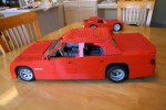
When I got out of college, I started getting back into LEGO; the end of my “dark ages.” I wanted to make a large supercar, just like everyone else. But after my first attempt, there were a couple of things I wanted to improve, and the first car did not really look right. OK, so what needed to change? I needed to stretch the car, and make the stance a little better, add some features, and make it as real as possible.
I used the dementions of the 2005 BMW 5 series as my template. From these demensions I used the F1 Racer wheels and tires to set the scale, then I determined the wheelbase, got the width, and I went to work. I first made the rear suspension unit, and then the dual cam V-8. Then I linked the two with a 4 speed transmission, and a long driveshaft and added a simple parking brake. It took a little work, but I then added the front suspensions. I have found it best to use technic beams to mount the front suspension. The A-arms are then attached to this structure, with the shock absorbers placed on this structure and braced with liftarms. I then connected this directly to the front of the V-8, and connected it to the rest of the chassis with a simple frame. I used the old steering mounts of the old 8865 supercar, and connected them to the steering wheel through an upside down mounted steering rack. Of note, the car was going to be big and heavy. I had to find a way to get two hard shock absorbers at each wheel which limited the suspensions options I had. In addition, I added a front and rear sway bar, which took a little more space, but it worked.
Then the body. I worked first on the doors, and the front bumper. I used a dual pivot design for the doors so they would open even though bricks do not work well with pivots. Then I did the front and rear quarterpanels, and set the rear bumper in such a way that a full size spare tire would fit. I then worked on the interior. I designed a simple tilt steering using a worm gear, and a universal joint. I made sure to use the great front seat design by Pixsrv, added a rear bench seat, funished the trunk and added all the little compartments in the center console and glovebox.
I finished with rest of the body work. The roof had a sun roof, and the trunk would have a damped shock to hold open the trunklid, and added small details and some mirrors. It was big, and it was done. I was pleased with my first large car. It still my most popular on Brickshelf.com.
All in all it was a great experience to learn about how to make a large car, and all the challenges that go with that. Frankly, since this design, most of my cars have been a little smaller, as it makes the suspension and steering work a little bigger. Lessons learned.
A couple of months ago I was struck by a new design by Waler. It was refreshing to see a well made Trial Truck based on something a little different. I wanted to make a model of my own. Thanks to him for the inspiration, and for the great ideas on the cab and the fenders.
From the beginning I knew this truck was not going to be a serious off road contender, but I wanted to redesign the whole drivetrain. I decided to go with a pendular suspension for the first and second axle and a trailing live axle for the third axle. All three axles would have a differential and a a set of portal axles. The first and the third axle would also have steering linked together. As is often the case with my trucks, I had the pendular axles held by a turntable with the steering function passed through the turntable by use of a differential. The second axle was held by a turntable in the front, and the steering differential passed through to provide steering to the final axle. The drive function powered all three axles and would connect to the transmission and motor in between the first and second axle.
The third axle was a suspended live axle that had a trailing setup created with the new 8110 pieces. This would allow for rotational and vertical articulation while connecting the drive shaft and giving space to the steering function above. The steering shaft would allow for movement via a CV joint. The Power Functions M steering motor was placed in the rear, and used a simple 1:9 reduction.
A Power Functions XL was used for the drive funtion and was placed between the front two seats. The motor was mounted on a sliding assembly for the gearbox function, much like the design pioneered by ATRX. I used my three speed changeover design to move the motor through three gears, for a final ration of 1:7.5, 1:4.7, and 1:3. The gearshift worked perfectly. While the drivetrain was a little complicated, the gearing was rather simple. The battery boxes were place above the second axle side by side. This kept the weight centered, and as low as I could get it.
Finally I added a cabin and a cargo area. The cabin was straight from Waler’s design, as was much of the fender area. I used technic panels to create the cargo area, which also gave me a space to place the two IR receivers. This also hid the two battery boxes, and the wiring, and generally cleaned up the truck. I created two small doors in the top to assist with picking up the ZIL. I was done.
Over mostly level ground the ZIL was one of my better designs. The differentials and steering worked flawlessly to make the ZIL drive easily. The gearbox worked well and eased the drivetrain over slight irregularities. But once the pavement turned to dirt the ZIL struggled a little more. It was not designed to have too much suspension travel, and this showed. It struggled on some of the bigger bumps, as the tires would scrape the wheel-wells. Overall, I was pleased with the design, and was happy with the way it turned out. It looked great, it was fun to build, and it was a blast to drive.
The full gallery can be viewed here. Also, a big thank you to The Lego Car Blog for posting this model on their blog.


