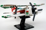
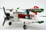
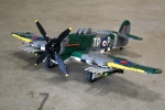
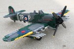
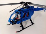
MD600N


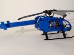
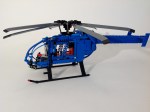
One of my first memories of a helicopter was watching a Phoenix Police MD520 land in Roadrunner Park, a block away from my house. The high pitch whine of the main prop was incredible, but another sound was missing. I gathered all my seven year old courage, and asked the pilot, “where is the tail rotor.” I got a lesson in aerodynamics that day, and to this day I can still identify an MD520 by sound. It still remains my favorite helicopter, so I figured it was high time for me to honor this aircraft in LEGO.

Full gallery can be found here. Instructions may be found here.

MD600N Front

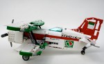
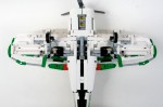
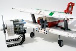
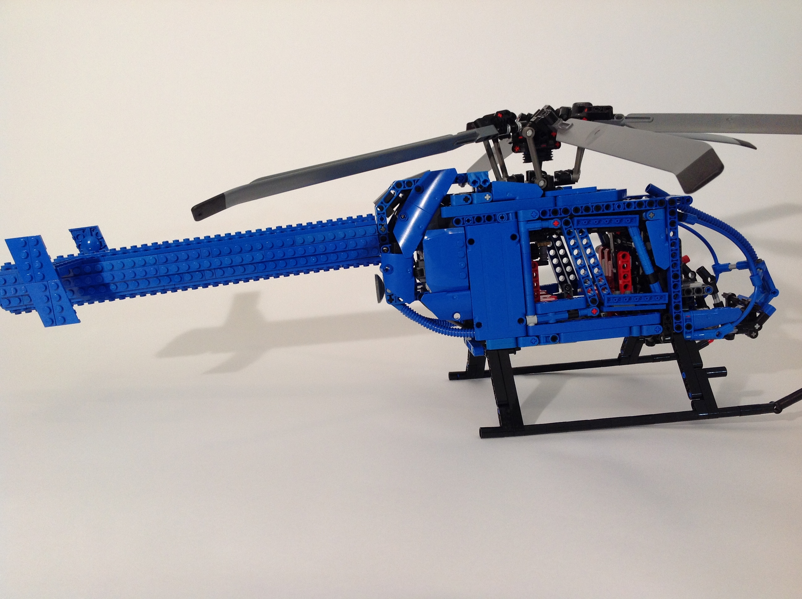
What excites me about building with LEGO Technic is creating functions that allow motor, movement, and control. Helicopters are mechanically complex, so I find myself drawn to recreating them. I learned about how they work when I built my first helicopter. With this new helicopter I started with the rotor head. I first built Effermans great swashplate design, and figured out what should stay and go. A four blade rotor head seemed not quite right, so after a little work, I managed to get a six blade head. It was with this decision, and discovering in the chosen scale there would be very little internal room, that I decided to switch to making an MD 600N.

MD600N Starboard

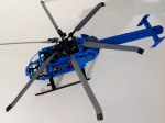
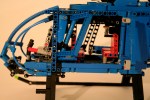
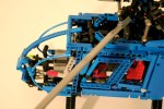
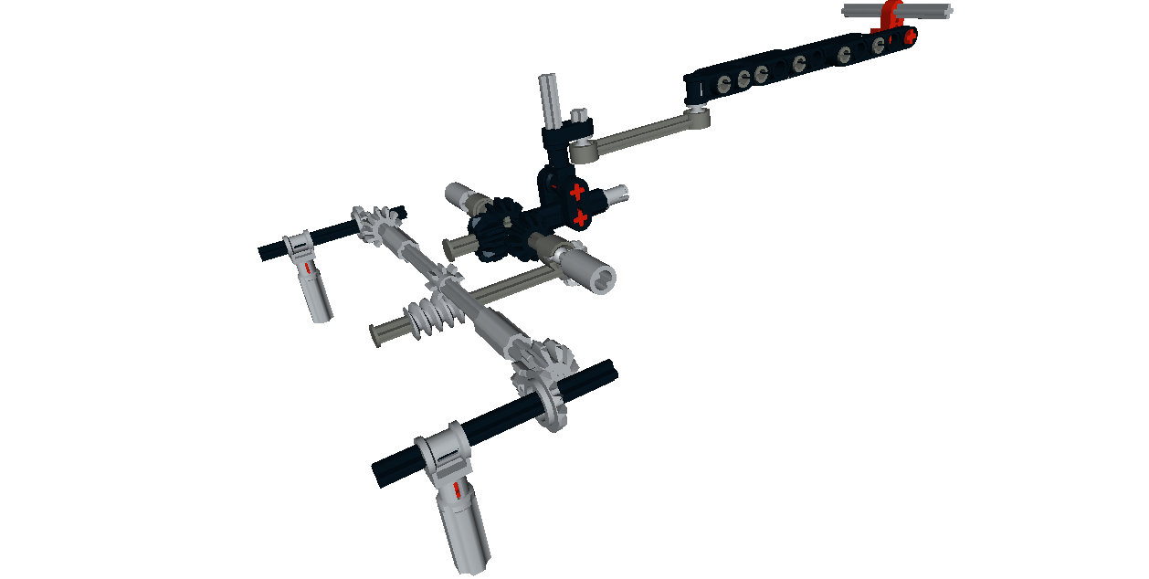
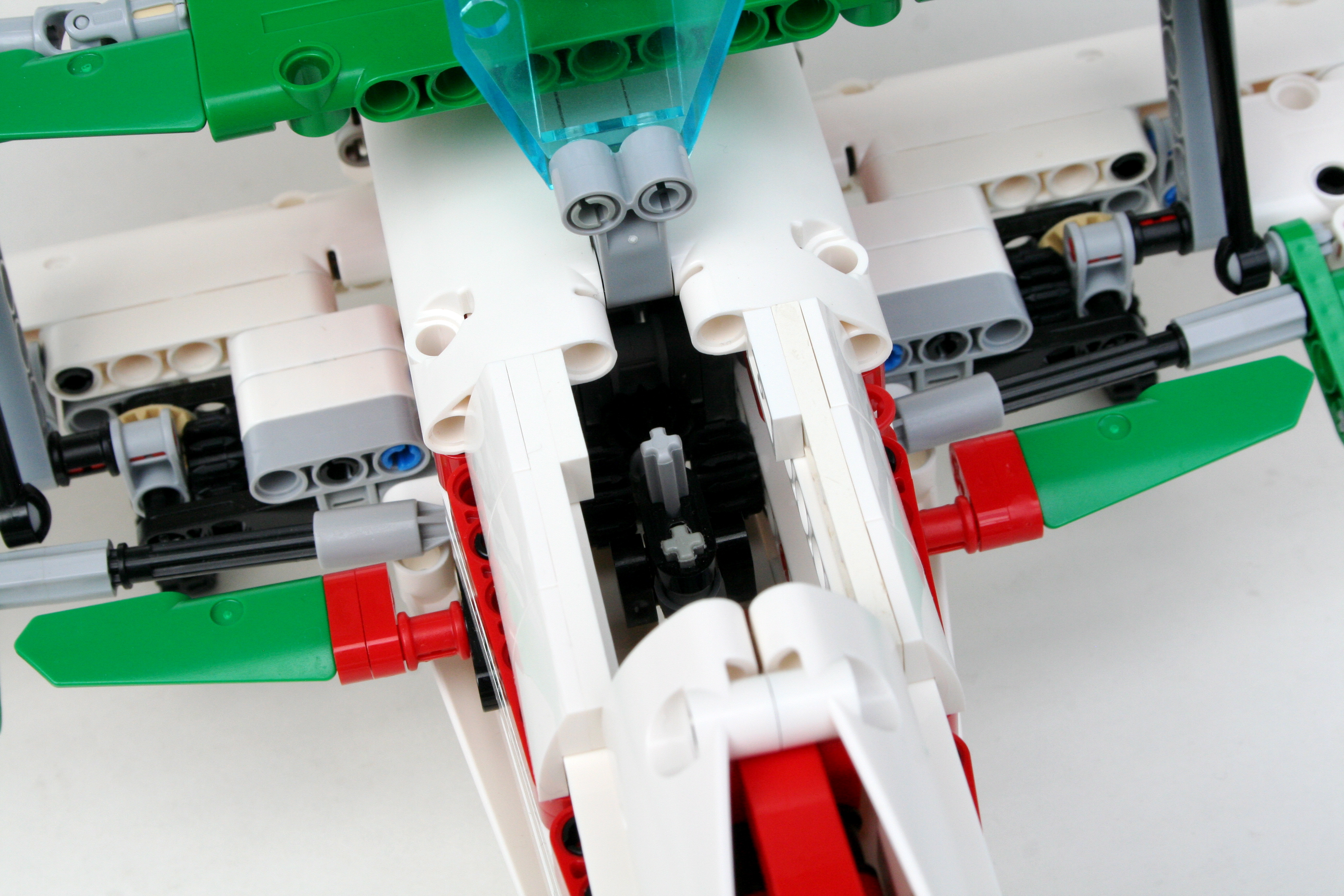
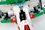
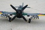
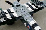
I then got to work setting dimensions, and getting the scale of the airframe correct. The length of the rotor blades dictated the scale, and the interior was going to be tight. The major challenge was getting the control functions connect to the cockpit. This is not a new challenge, as it seems to be the case with every large plane I do. I have a lot of experience with it, and so I came up with some solutions. The challenge with a helicopter is the collective. Every movement that is transmitted, must be able to retail its movement while also being effected by the collective. This works well with the swashplate, but at the controls is where this gets difficult. Using the basis of Effermans design allowed for a simple setup where the collective moves an axle on which the the left/right and fore/aft controls mount.

MD600N Cockpit

_MG_2539

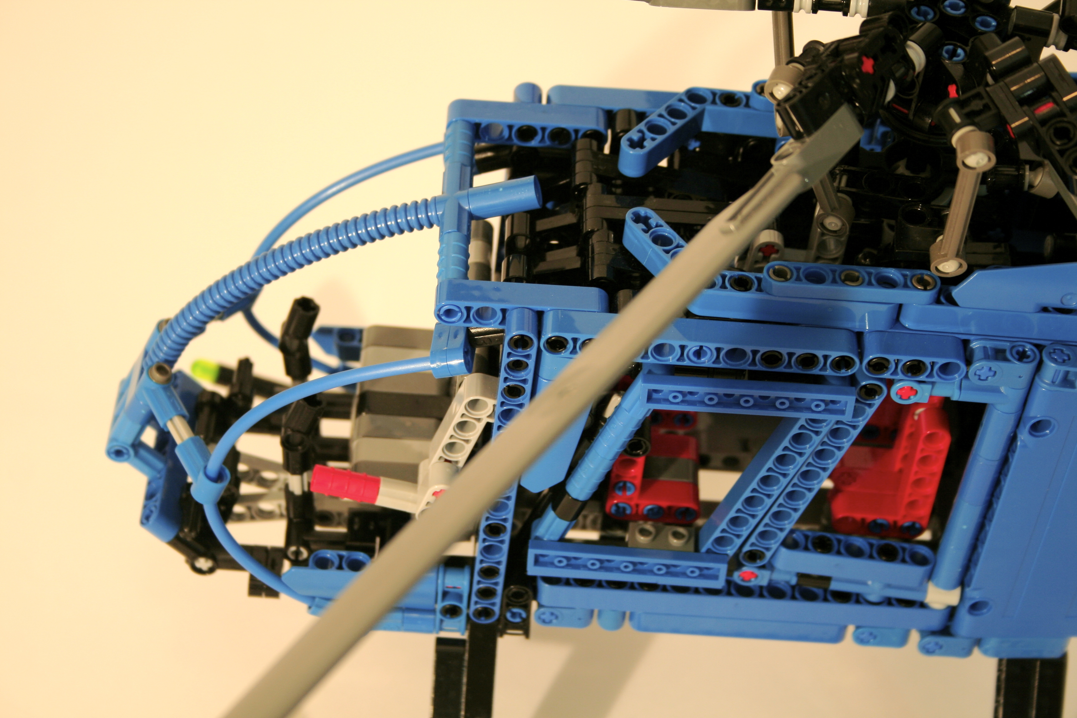
Moving the collective moves the other two controls in a way that is independent from joystick inputs, and allows for complete swashplace articulation at any collective pitch. The controls connect to the swashplate above the main cabin and move forward. From there all three fuctions move down to the floor of the cockpit in between the pilot/copilot seats, and the second row seats. The collective is connected here to a lever on only the pilot’s side. The left/right controls connect via an axle to the joystick, and the fore/aft controls connect via a 9L link to the joystick. Both joysticks are linked together.


MD600N Chassis

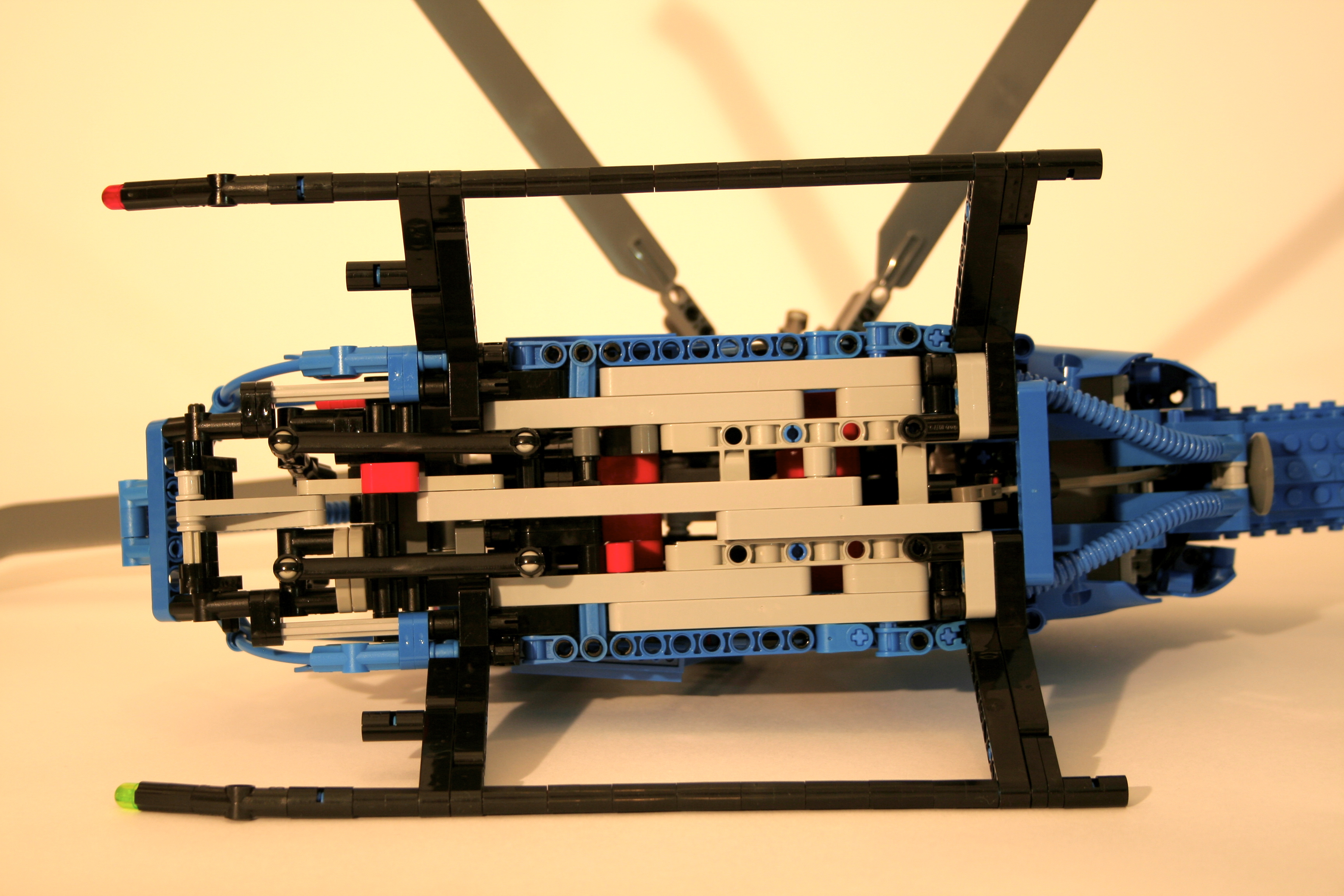
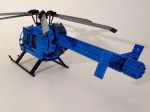
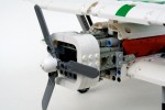
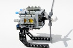
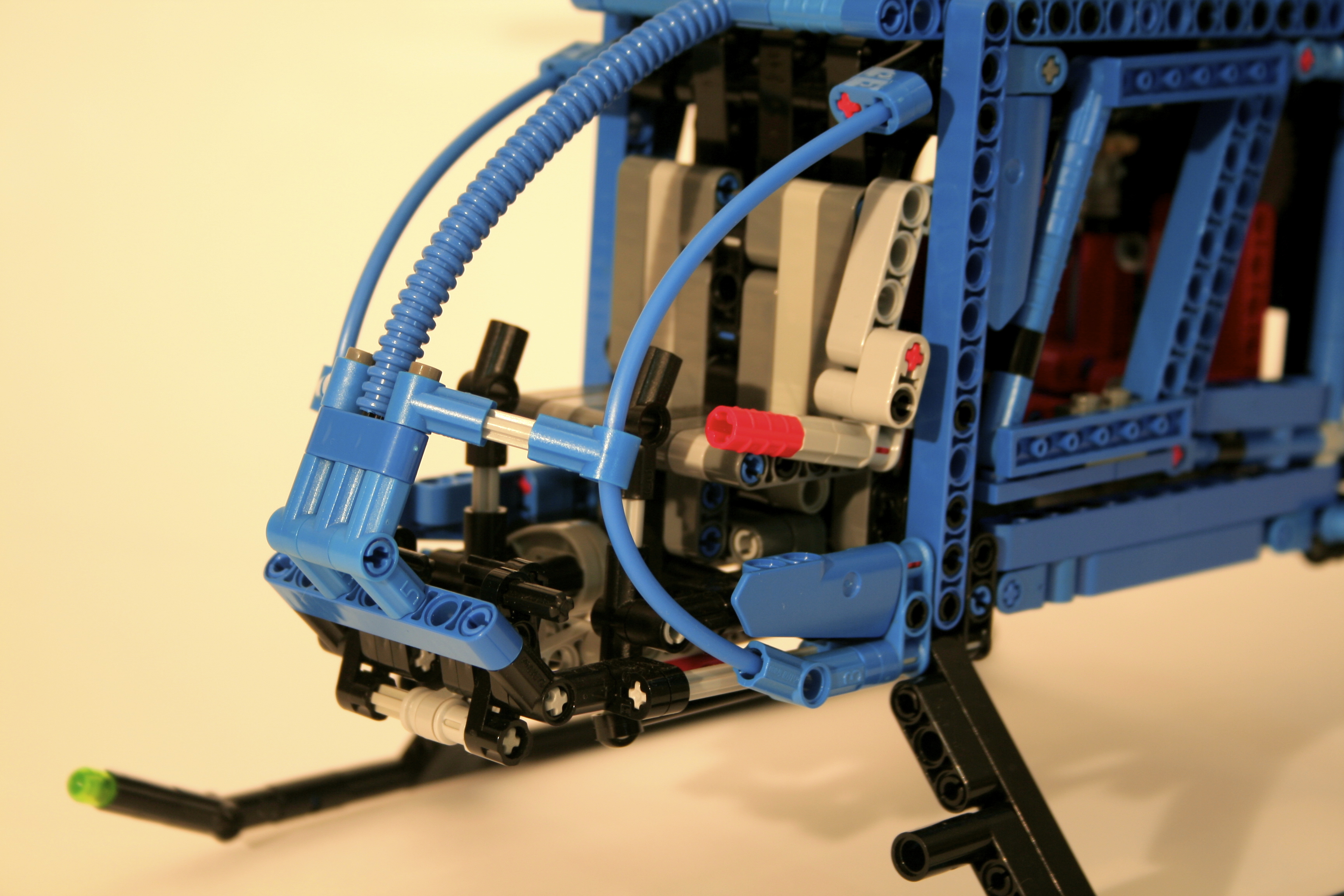
The final control adjusts the yaw of the aircraft. The MD600N uses three methods to give anti-torque to the main rotor. In forward flight the 1)  tail planes give directional stability. The tailboom also has 2) two slits that provide a “Coanda Effect” from the main rotor downwash. Finally, at the end of the boom is a 3) movable jet direct thruster (all are nicely discussed here). This thruster rotates to force more or less thrust against the torque of the main rotor, much like the more common tail rotor. In this MOC, the thurster rotates on a small turntable, and has an axle running through the boom the controls the rotation. The axle connects to the floor petals by way of a flex cable, and a liftarm running below the cockpit. Both pedals are linked together.

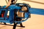
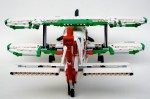
Once all the controls were set, I could work on the body. I wanted the helicopter to be blue as I see it in my memory (almost). This presented some parts challenges, but not as many as I expected. The two suicide doors open to the main cabin, though I did not add any to the cockpit. Many liftarms and connectors were used for the rest of the cabin. I wish current Technic parts could facilitate the rather bubbly lines of the MD600N, but I was pleased with how it looked in the end.

As with many of my large aircraft, this helicopter suffered from gummy controls. The range of motion of the controls reflect the scale for the model, but do not allow for great playability or demonstration of features. For something like a helicopter, I am interested in powering the controls surfaces and inputs controls via Power Functions much like this. Next time I guess. But the Helicopter looks great on my shelf, and it brings me back to a great time in my childhood. I hope you enjoy.

Happy building.


Advertisement

OCTAN Air Racer


OCTAN is one of my favorite longitudinal themes of LEGO. It gives a little color and identity to many of the racing vehicles that have been produced by LEGO since 1994. I don’t know why it took me so long to start making MOCs with an OCTAN theme, but after last summer’s OCTAN F1, I figured I should do another one.

The full gallery including instructions may be seen here.

OCTAN Air Racer

It was time for me to build another airplane, and I figured a0 small air racer would work well in the OCTAN colors. Right from the beginning, I was sure I wanted to make a biplane, and I wanted a radial engine (all real airplanes have propellers). From there everything was on the table. Off to designing.

I started with the radial. It’s not quite a radial, but rather two perpendicular boxer 4 cylinder engines. Each bank of two cylinders are mounted in a different direction; up, down, port, and starboard, and are connect by one common crankshaft. The side banks are one stud forward, and the up and down banks rear, so all eight connecting rods can fit on a common 5l axle. Two engine crankshafts are mounted at each end. The motor spins well, and quite quickly, but the connection is not exactly “legal,” as the pins on the cylinders are a little stressed.

8 Cylinder Radial

Working backwards, I attached the leading edges of the wings, and the worked on the landing gear. Being an air racer (even a biplane), it had to have retractable landing gear. I connected the two wide spaced legs with a simple axle and bevel joint, and added a worm gear to articulate the action. It is a simply solution, and it functions well.

Air Racer Bottom

Just behind and above the worm gear is the joystick. The roll functions are connected to the bottom wing by gears, and the pitch function is connected by liftarms to the rear elevator. The rudder is fixed. The lower ailerons are connected to the upper ailerons by a simple 9L link. When you move the joystick, all four ailerons move. The cockpit is a little cramped, but when you are racing space is not a concern, only speed.

Air Racer Drive


Air Racer Cockpit

After the radial, the bodywork was the priority for the MOC. I have been slowly acquiring white and green parts over the last year. The airplane was designed as primarily white, with red and green accents. The red stripe worked well, as did the red tail, but I could not find a great way to incorporate the green. I added a little to the tips of the wings, and to the wing control surfaces. I used a couple more stickers that I had left over from set 60025, and the MOC was finished.

I was pleased with how the MOC turned out. The airplane looks strong, and the red and green make the white vibrant. I wish I could have found a better place to incorporate the green. The places it was added seems a little haphazard. The radial turned out great, but I feel a little bad about the illegal build. The landing gear works well, as do the control surfaces. I was pleased with how it turned out. Next up, maybe an OCTAN speedboat. Other ideas?

Happy building.


Hawker Typhoon MkIb


Two years ago I built the Spitfire MkIIa. It remains one of my more popular builds, and one of which I am still quite proud. It was not my first large plane, though when I completed it, I said it would be my last.

As my father would say, “never say never.”

Typhoon

The full gallery may be seen here.

I learned a lot of great things from the Spitfire. Large scale building is exciting, and challenging in that you have to think about significant structural considerations, placement, and shaping before and while your build.

With this in mind, I wanted to develop what I have learned, but allow myself the ability to take a large scale aircraft to the next level. I wanted to improve the function of the control surfaces, design my own propellor, use four Power Function channels, and use the boatload of Dark Green parts that I had recently acquired. I considered a number of airplanes, including doing the FW-190 again, but I finally settled on the Typhoon. Time to get building.

After some planning, I had my scale. 1/13 was an appropriate size for me to replicate the plane and its functions, while still keeping the plane from getting too large. This scale would also allow for LEGO wheels for the landing gear, and a worker able propellor spinner design. As I learned from the Spitfire, placement of large components needed to be done early, and placed in the MOC to its exact final location. As the structure of the fuselage and wings would be stressed heavily, large components could not get in the way. Once I placed the engine block, the landing gear, the power functions, and the control surfaces, I was able to start putting together the robust structures that would support the final plane. One of the major challenges of this plane was the outset landing gear on the wings. Because they were located 42 studs apart, the wings needed to be strong. But due the the space taken for the control surfaces, and the massive 24 cylinder power pack, the wings still sag a little under load.

The control surfaces were activated with strings with studs on each end. I found this to be a better system than the axle controls for the Spitfire. It kept the controls more smooth, and reduced the amount of play in the controls. The elevator and ailerons were controlled with the joystick, and the rudder was controlled by two foot pedals in the cockpit. The remaining functions were controlled via Power Functions. An XL motor powered the massive 38 stud diameter propellor, as well at the 24 cylinder Napier Sabre engine. A M motor controlled the pitch of the propellor. Another M motor powered the landing gear, and still another  adjusted the flaps. All four motor were mounted in the chin of the aircraft; I had to use that huge chin for something. The two IR receivers were mounted in under the windscreen, and the rechargeable battery was mounted behind the cockpit.

Finally, I had to make sure all the markings were accurate. Again, due the limits of dark green parts, it was not an easy task. I started with wings, and made sure to add invasion stripes, and work my way out to the tips. The roundels were a little different than the Spitfire, but were a little larger. The fuselage took a little work to make sure the panels could be easily removed, but I eventually got there. The fuselage roundel should have a yellow ring around the outside, but the strip is so small, I could not figure out a good way to do it.

The plane worked almost perfectly. The ailerons were a little sticky, but other wise everything else managed to work for an 8 hour shift at Brickworld. The plane was liked enough to be nominated for Best Air Ship. While it did not win, it was validation that the the model was a success.

Happy Building.

Focke-Wulf FW-190 a5


I start most of my projects because I see something brilliant by another builder, and then I decided to develop this idea, or give the idea little more substance.  After discovering a great two row radial, I wanted to give the engine a body.  It had also been a long time since I had done a large project.

I chose to make the FW-190 for a couple of reasons.  First, it had a radial.  OK, 14 cylinders in the plane, and mine would only have 12, but it was close enough.  Second, it was one of my favorire plane of WWII.  Third, the body work would not present too many challenges.  I set to work.  I had to get the scale right, and start placing some of the plane’s extremities, so I would have a good idea where to place all the parts that I would build.

Once everything was placed, I had to figure out how I was going to do all the control surfaces.  This started with figuring out the joystick, and the rudders.  The joystick was a simple design driving side to side movements out the front by an axle to gears for the ailerons.  When the joystick was moved front to back, a link all the way to the rear elevator was activated.  I mounted the foot pedals on a simple pivot connected by gears to the rear rudder.  Flaps, with a simple activating lever, were also installed.  The cockpit was pretty full.

With a project this size, it took a great deal of work to get the shaping of the plane to work right.  I used half stud offsets to get the fuselage correct, and spent a lot of time on the wings.   Because the cockpit had a lot of activating levers, a lot of work went into the area around here.  Adding the opening canopy did not help things.  I added brick built markings, worked on the coloring, and spent some time adding guns and other details.  The model was done.

Brickshelf.com gallery is here.

It’s been three years since I have built this plane, but I needed a little motivation to help me with another similar project.  It was good for me to remember how much I enjoyed this project, even though it took a lot of time and energy.  Stay tuned for the next big plane.