Rumble Bee


It has been six years since I bought my F1 Wheels and Tires.  I bought four, and I paid a lot for them.  To date, I have used them once in my Red Sedan; and only two of the four that I own.  For some reason, I decided I needed to use them again and I wanted to do a small little project.  I was recently reminded about a childhood video game P.O.D. racing, and thought the car I was designing would fit right into the game.

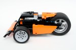
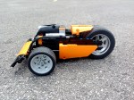
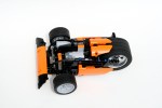
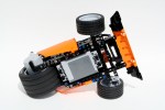
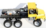
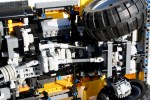
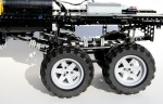
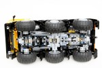
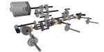
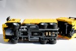
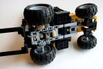
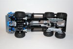
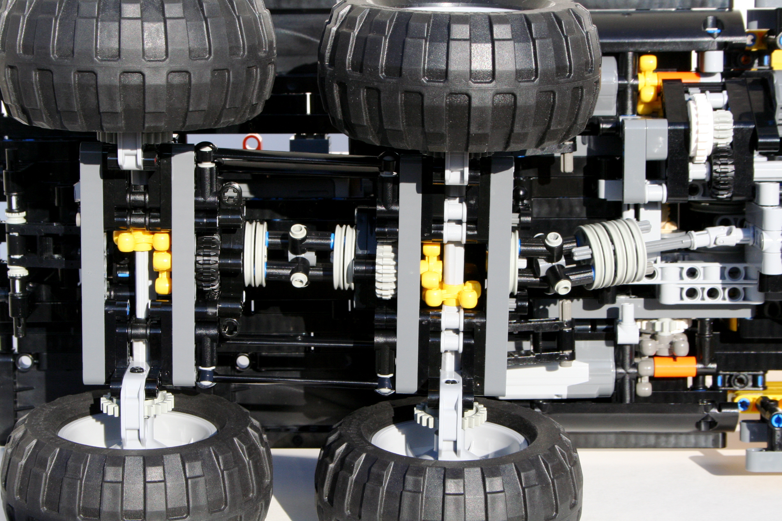
The car is a simple design; a drive motor, a steering motor, a battery box, and a receiver.  I knew I was going to design a three wheel car.  I wanted to have the rear wheel driven by a PF XL, and a single PF M with a simple return to center system for the steering.  After a couple of designs, I decided to place the PF XL motor in the hub of the single rear wheel.  I tried a couple of designs to gear the motor up for a little more speed, all with various locations in the car.  Nothing worked as well as I wanted.  The speed was sufficent, and placing the motor in the hub allowed for a super short wheelbase.

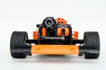
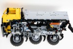
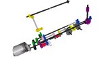
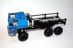
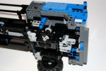
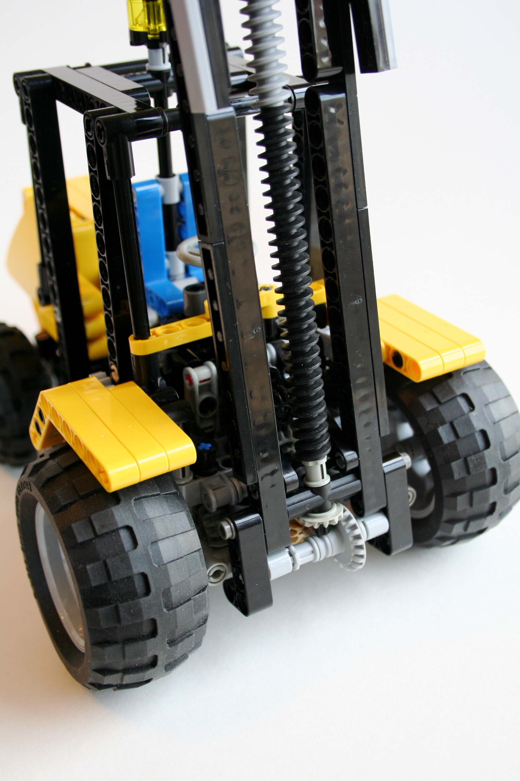
Because the PF XL was place in the rear, I had a lot of space for the rest of the Power Functions equipment.  I placed the battery box directly in front of the rear wheel right at the bottom of the car.  The front steering axle was place next in front of the battery box.  The car had a short wheelbase of only 18 studs.  On top of the battery box, I placed the PF IR reciever and the PF M motor which was for the steering.  The steering motor passed an axle straight through a Spring Loaded Connector to move a 3L liftarm which connected to the steering rack with a 6L steering link.

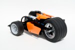
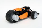
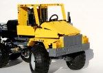
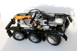
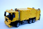
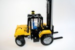
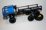
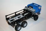
I added a simple body using the orange panels from 8110.  Keeping with to story of P.O.D. I wanted to keep an agressive stance and look to the car.

The car ran well, and was plenty quick.  The steering was sharp and the car was well planted on the road.  I had a good time with the design.  Now I need to come up with another use for my F1 wheels.

The full gallery may be found here, and instructions here.

Freightliner M2


For some reason, I often find myself building two trial trucks at the same time.  While I was building my ZIL 132, I also wanted to try something with floating axles.  The model would use 6 wheels, a 3 speed transmission, and fully suspended live axles.  I also wanted to model the Freightliner M2 Business Class truck as closely as I could.

The model started as my trucks usually do; with the axles.  The second and third axles would be identical, and would be connected with a simple pulley wheel universal joint between the two.  To keep the speed through the universal joints high, and the torque low, I used as 12z/20z gearing after the universal joints, then the knob wheels to rotate the axis, then the normal 8z/24z gearing on the portal axles to finalize the drive.  This also allowed me to keep fewer knob wheels as the second axle had the drive shaft from the transmission pass uninterrupted to the rear wheels.  The final drive ratio for the two rear axles were 1:5.

The front axle was a little more work.  I wanted to have the steering motor mounted on the axle so I would not need to have a steering shaft connect to the front axle.  This proved too difficult, as it would raise the PF XL motor that I was going to use for the drive to high on the truck.  I decided it would be better to mount the steering motor on the frame and connect to the front axle via a CV joint.  Once I made this decision, the front axle became easier.  I used a 1:3 gearing on the portal axles, a knob wheel, and then a drive shaft back to the transmission.  The steering axle would exit just above the drive shaft on the axle to move to the right for the steering motor.

The frame was pretty simple.  Once I had the transmission placed, and the axles spaced, it was simple to place the suspension components, and the shock absorbers.  Each axle had two steering links mounted vertically which connected to a 3×5 liftarm which would activate a shock absorber; very much like Lyyar’s design.  Each axle had a steering arm to keep the axle from swaying laterally.  Finally, all three axles had a number of 9L links to keep the various movements maintained.

The transmission was going to be placed behind the PF XL motor which was under the hood.  The changeover mechanissm would be placed in the center of the truck with the changeover motors mounted longitudinally, on both sides of the truck.  The PF XL motor was place directly above the first axle, and was mounted on a moving frame that was moved by the changeover.  This allowed a moving frame to work its way through the three gears.  The ratios were 1.25:1, 1:1.25, and 1:2.  This allowed for final ratios of 1:4, 1:6.25, and 1:10, which was more than capable for most terrain.  The drive and steering Battery Box was mounted over the second and third axles, and the gearbox 8878 battery box was just behind the changeover in a little box on the bed of the truck.

Finally, like always, a simple body was mounted.  I had a little trouble getting the look I wanted on the front of the hood, as the suspension components kept getting in the way.  I added a bed, covered the changeover and motors, and a couple more details and everything was finished.

The model was not my best driving truck, as six axles do not want to always work together.  The suspensions was supple, and I was getting no drive or steering input on the suspension.  The truck worked well over various terrain, but struggled on some on step obstacles.  The transmission mounting worked well at changing gears, but gears did not have a strong support, and I found they liked to skip at times.  I liked how the suspension worked, but I do not think it brought enough of a valued to use this system again.  It had moderate improvement on dealing with terrain, but it placed a lot of stress on a number of parts, such as the frame, the axles, the driveshafts, and the universal joints.  The next truck will use a pendular set up again.

The full gallery may be found here.

Zil 132


A couple of months ago I was struck by a new design by Waler.  It was refreshing to see a well made Trial Truck based on something a little different.  I wanted to make a model of my own.  Thanks to him for the inspiration, and for the great ideas on the cab and the fenders.

From the beginning I knew this truck was not going to be a serious off road contender, but I wanted to redesign the whole drivetrain.  I decided to go with a pendular suspension for the first and second axle and a trailing live axle for the third axle.  All three axles would have a differential and a a set of portal axles.  The first and the third axle would also have steering linked together.  As is often the case with my trucks, I had the pendular axles held by a turntable with the steering function passed through the turntable by use of a differential.  The second axle was held by a turntable in the front, and the steering differential passed through to provide steering to the final axle.  The drive function powered all three axles and would connect to the transmission and motor in between the first and second axle.

The third axle was a suspended live axle that had a trailing setup created with the new 8110 pieces.  This would allow for rotational and vertical articulation while connecting the drive shaft and giving space to the steering function above.  The steering shaft would allow for movement via a CV joint.  The Power Functions M steering motor was placed in the rear, and used a simple 1:9 reduction.

A Power Functions XL was used for the drive funtion and was placed between the front two seats.  The motor was mounted on a sliding assembly for the gearbox function, much like the design pioneered by ATRX.  I used my three speed changeover design to move the motor through three gears, for a final ration of 1:7.5, 1:4.7, and 1:3.  The gearshift worked perfectly.  While the drivetrain was a little complicated, the gearing was rather simple.  The battery boxes were place above the second axle side by side.  This kept the weight centered, and as low as I could get it.

Finally I added a cabin and a cargo area.  The cabin was straight from Waler’s design, as was much of the fender area.  I used technic panels to create the cargo area, which also gave me a space to place the two IR receivers.  This also hid the two battery boxes, and the wiring, and generally cleaned up the truck.  I created two small doors in the top to assist with picking up the ZIL.  I was done.

Over mostly level ground the ZIL was one of my better designs.  The differentials and steering worked flawlessly to make the ZIL drive easily.  The gearbox worked well and eased the drivetrain over slight irregularities.  But once the  pavement turned to dirt the ZIL struggled a little more.  It was not designed to have too much suspension travel, and this showed.  It struggled on some of the bigger bumps, as the tires would scrape the wheel-wells.  Overall, I was pleased with the design, and was happy with the way it turned out.  It looked great, it was fun to build, and it was a blast to drive.

The full gallery can be viewed here.  Also, a big thank you to The Lego Car Blog for posting this model on their blog.

Mercedes Benz Axor Refuse


I am a big fan of garbage trucks.  For some reason I find the combination of a smaller truck,with many features all with a complicated compaction device is a great basis for a complicated LEGO Technic model.  Plus, trucks are fun.

The hardest part was going to be the rear compaction device, so that is where I started.  I decided to use a Geesink Norba design as it would give me the largest opening for the trash in the rear because the mechanicals would be on the bottom on and the top of the opening.  13 studs wide is not much space.  In addition, this would allow me to have the rear hopper pivot up to let the trash out when it was full.  I would need to have three functions going though the pivoting hopper.  One at the pivot, and two connecting at the base when the hopper was closed.

The dumpster lift would be driven through a knob gear when the hopper was closed on the bottom.  The compation device would be operated with a gear on the bottom and a mini linear actuator on the top.  This mini linear actuator would also function as the opener for the rear compactor.  All the motors would be housed on the bottom, with one motor placed next to thebattery box.  The extractor would be operated by another mini linear actuator using a scissors mechanism to move the ejector plate.

The chassis was constructed with a PF XL in front of the steering axle.  The motor would power both the drive, and the extractor changed by a changeover.  The steering motor is placed on the right of the truck.  On the left, another PF M motor powers both the dumpster lift and the lower hopper compaction device.  All power came from a 8878 rechargeable battery box, through two PF IR receivers, and powered four motors: One XL for drive and the extraction plate, one M for steering, one M for the dumpster lift and lower compaction, and one M for upper extraction and hopper opening.

The model worked well, particularly steering and the drive.  However the extraction and the hopper opening was a little less reliable.  The hopper was too heavy for a single mini linear actuator, and the compaction device was not stiff enough.  It happened to get caught on some of the internal edges on the inside of the hopper.  The next garbage truck will need to be built a little more sturdy.

The full gallery may be seen here.

JCB 930 Forklift


It was time for me to to make something that was a little smaller with a lot of functions.  I kept driving by a JCB forklift on the way to work, and I thought I could make that.  I wanted manual functions, including a working fork tilt and dual stage lift, working steering and drive, and a yellow bodywork.

I always start with the hardest part of a model.  For this model, that was the fork.  I wanted to use a dual stage lift as to get the forks to a substantial height.  This design would require a chain that would wrap over a moving frame, and connect on one side to the forks, and on the other side to the body.  The moving frame would be moved by a screw, thereby lifting the forks.  I used a number of worm gears on two 12l axles, connected through the bottom to move the moving frame.  This setup allowed for a pivot point, and a lifting mecanism that would function much like the real JCB 930.  The moving frame consisted of two rows of liftarms, and the forks tied everything together between the moving frame and the worm gears.  A chain went up and over the full assembly to work move the forks as the moving frame was lifted.  It works like this.

I then worked on the driveline.  I added a 3 cylinder motor in the rear, driven by the front wheels, working to keep the functions out of the way of the fork mechanism.  I added a steering axle on the rear, and gave it a pendular suspension setup.  This allowed for some stability on uneven ground, while keeping the front wheels planted for the load as it had no suspension.

I then built the body after the JCB 930, and as I did, I added a tilt freature to the fork.  This feature did not work too well, but it gave me the ability to adjust the pitch of the forks, which we a design requirement.  It was not too stable.  After a little work to the body, and a HOG steering link out the top of the cab, the model was done.

The model worked well, particularly the lift feature.  I was a little disappointed with the tilt feature, as it was a little too wobbly. The drivetrain worked well, and the steering allowed for tight corners.  The suspension give good stability, and offered a little bit of off-road prowess.

The full gallery is here.

LMTV Mini Truck Trial


As I start this new blog, I thought it may be helpful to post some of my older models to show what I have done, and give a little history to my designs.  In the midst of getting into Trial Trucks, I decided it was time to make a new smaller truck.  I designed a mini truck, to test my abilities with smaller functions based on the Oshkosh LMTV military truck, and to take my mind off the design that was taking most of my time.

I chose the six wheel truck as it would make the suspension of the truck a little more simple than other designs.  The rear axles would be tied together on each side, with a pivot point in between each wheel; one for each side.  A single axle would connect both sides through the dual pivot points, and would be powered by a worm gear directly from the drive motor.  This set-up did not require any additional suspension components, and this would allow the front axle to use an unsuspended pendular set up.  The PF M drive motor was placed above the rear wheels and drove an axle that would go to both the front and rear axles.

Like the rear, the front axle would use a worm gear directly from the motor to drive the wheels.  From the worm gear, a 8z gear was used to drive two 12z double bevel gears for each wheel.  Both 12z gears would drive two more 12z double bevel gears to which allowed for drive through the steering axis.  A simple link connected the two steering wheels, and used a rack and pinion setup to transmit the steering function.  It worked well, and allowed the steering motor to slip at steering lock.  A PF M steering motor was placed above the front axle in the cabin.

I created a small bed, and cabin for the truck and decided to build the truck in blue.  As I was browsing through my Brickshelf folder, I noticed I had too many red vehicles, so something blue would be good.  I placed the 8878 battery box, and PF receiver between the cab and the bed.  This allowed for proper center of mass, and gave me a fully functioning bed.

The model worked well.  For such a small vehicle, it took a lot to stop the truck, in part because of the worm gears.  The steering worked well, but the turning radius was limited, due to the poor steering lock.  I was a fun model, and it is still one of my more popular projects on Flickr.  See the full brickshelf gallery for a more complete view.