Ionos Sport Sedan
January 8, 2022 1 Comment
Sometimes I cannot make a decision. This is the LEGO result of that problem.
You may find free instructions for the AWD and the RWD (my favorite).

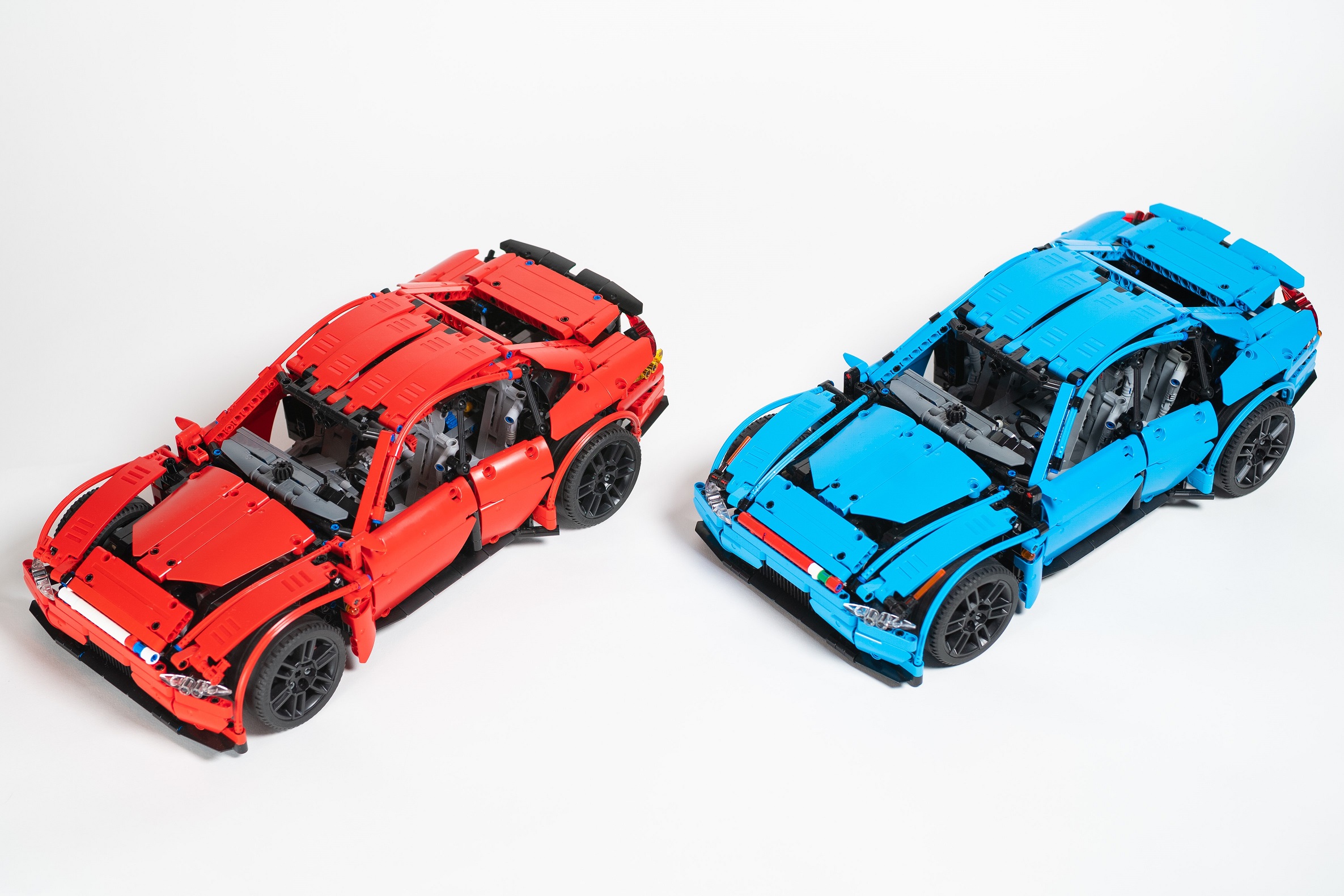
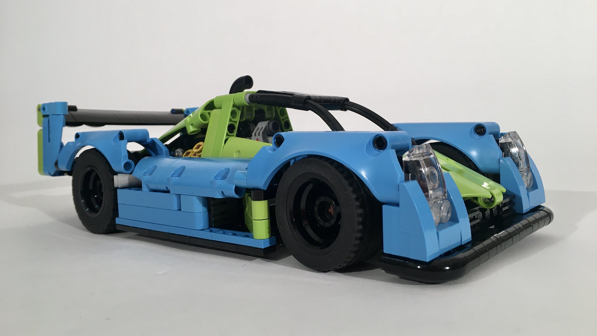
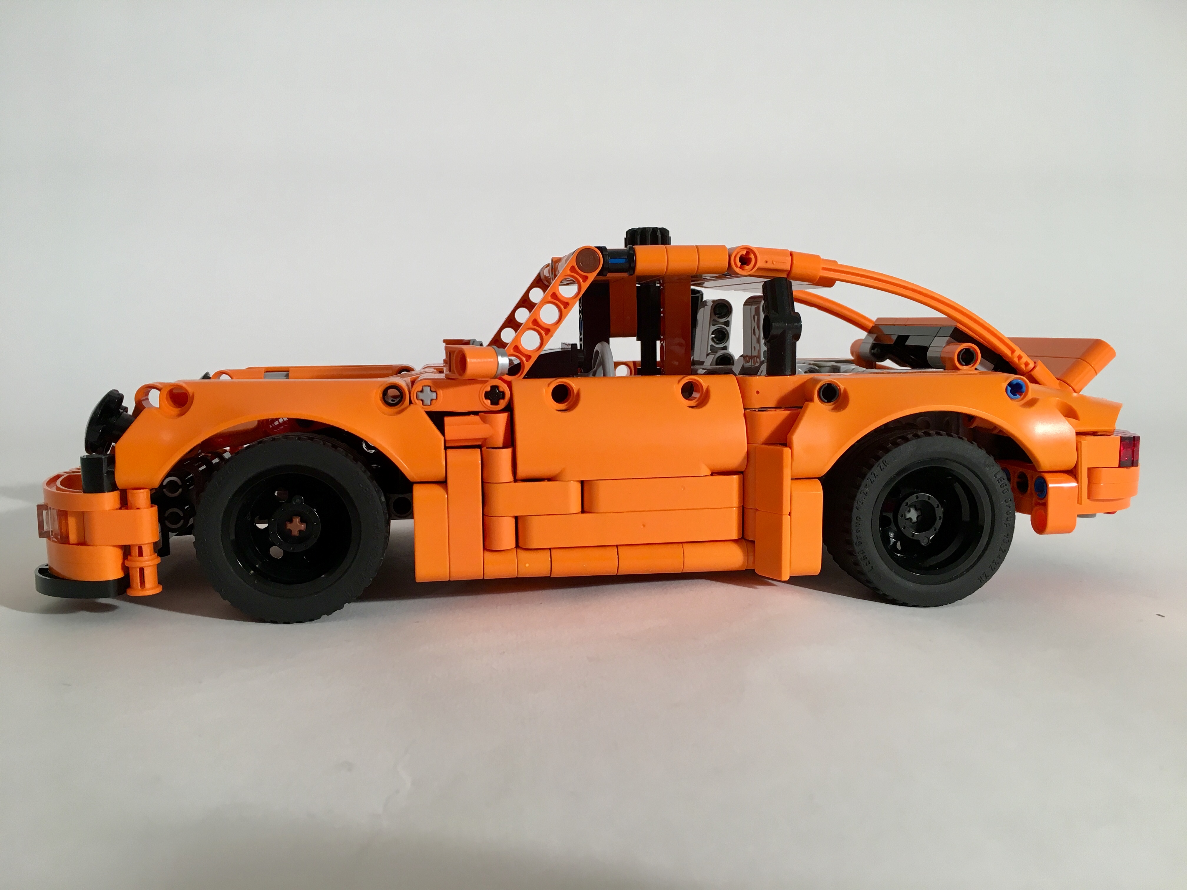
At the end of 2020, I decided to make a sport sedan. I find the sport sedan to be my favorite kind of car (see here and here), and it was time to do another one. I acquired a couple of the Defender wheels, which look more sporty than the other 56mm wheels. These would be the center of the build. The car would be long hood, short deck, with faired fenders. Then more questions happened, and I could not make up my mind.
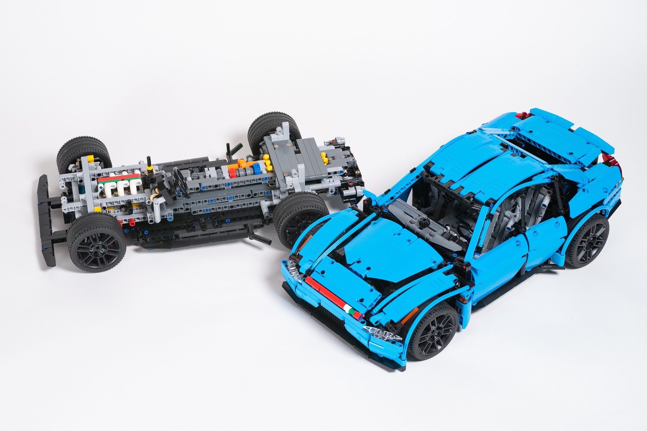
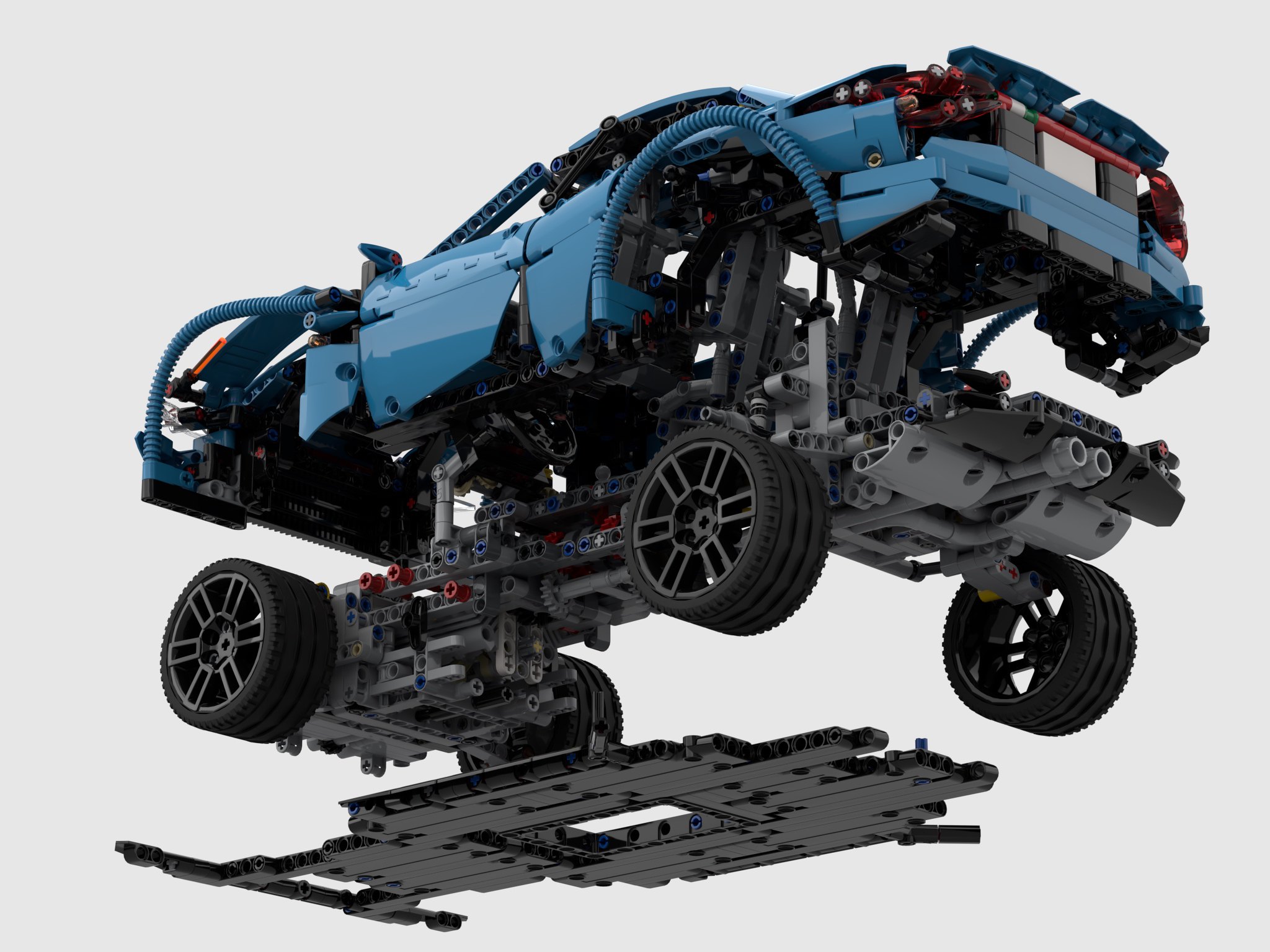
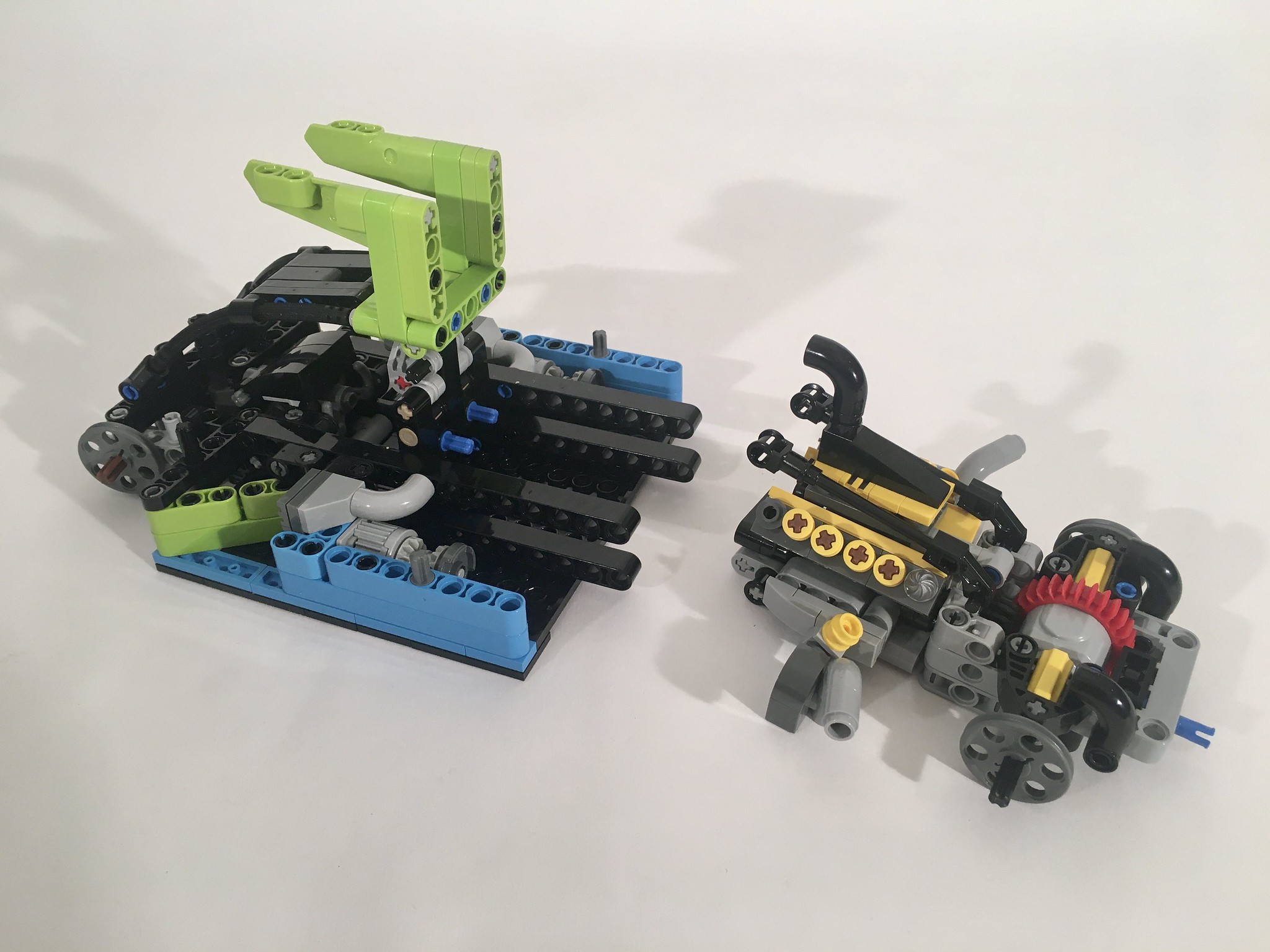
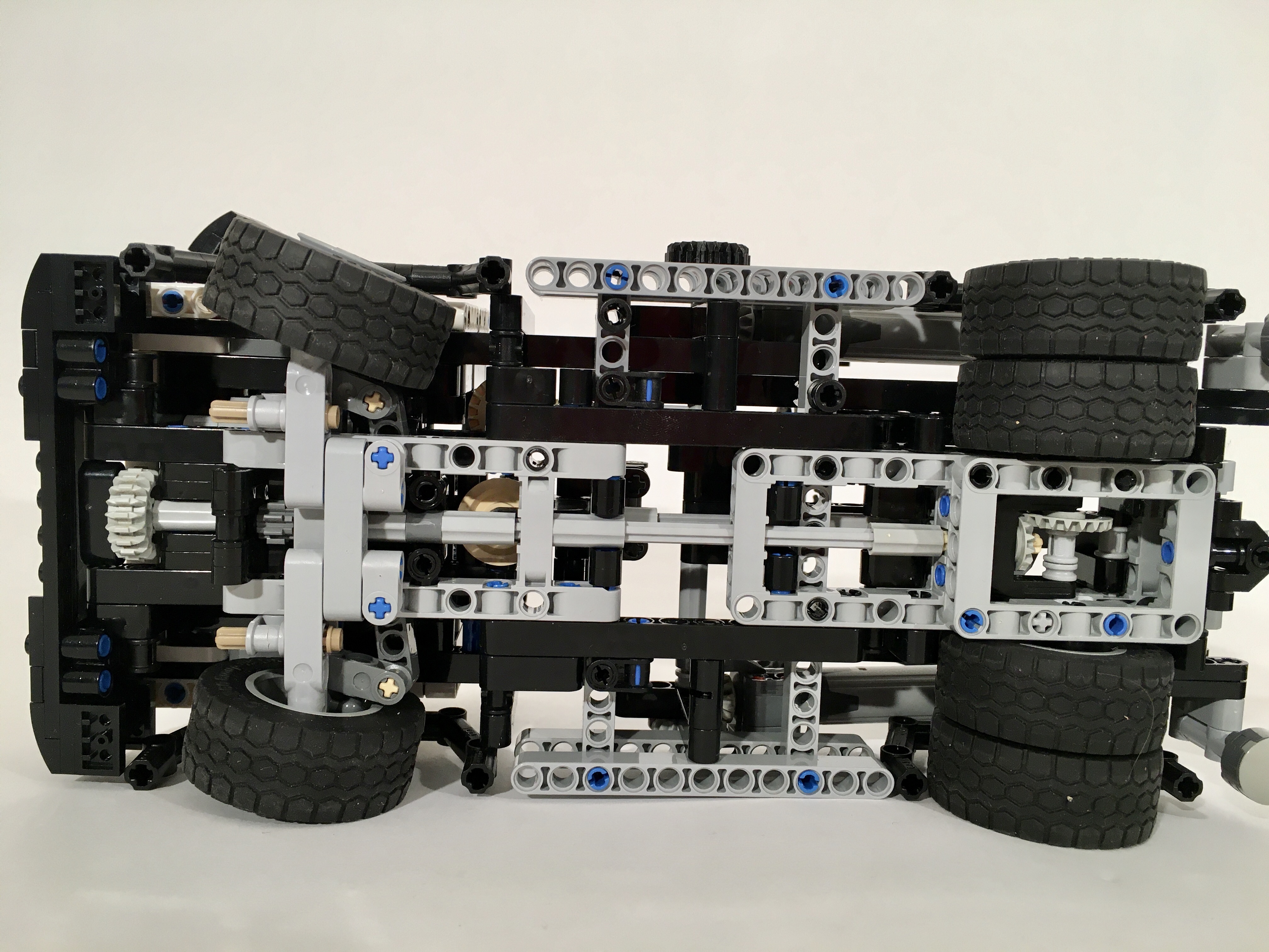
What transmission did I want? What engine would be best? Could I fit all wheel drive? Was that appropriate? As I found myself asking these questions, I began answering “well why not that too?” It was here, the project took a dramatic turn. The car would be fully modular and interchangeable. After playing around with some dimensions and simple structures, I decided on the following setup: Two different transmission and rear suspension modules, one floorplan, one body (in two colors), two engine tubs for all wheel drive and rear wheel drive, and three engines. Demensions were set with a width of 27 studs at the rear tires, and 25 studs at the front tires, and a wheelbase of 33 studs.
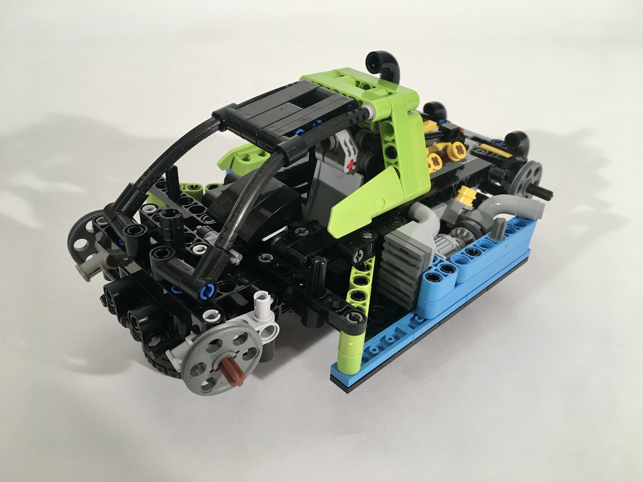
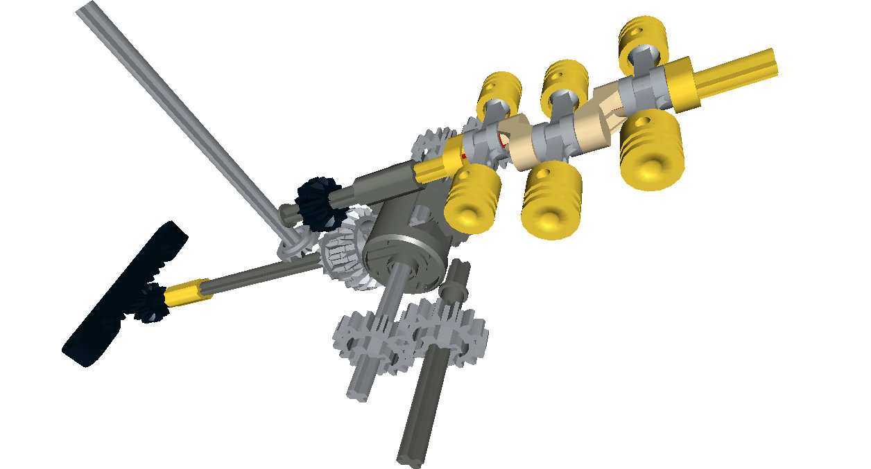
Each of the 9 modules were build in constant flux with each other as I managed attachment points, size, and interchangeability. I settled on a 4 speed manual transmission module, and a 4 speed sequential transmission module. The manual is shifted in the cabin, and the sequential has a shift lever on the rear bumper. While four speeds is basic for a LEGO car these days, it kept space inside for four seats. Once the transmission modules were basically set, I was off to another module.
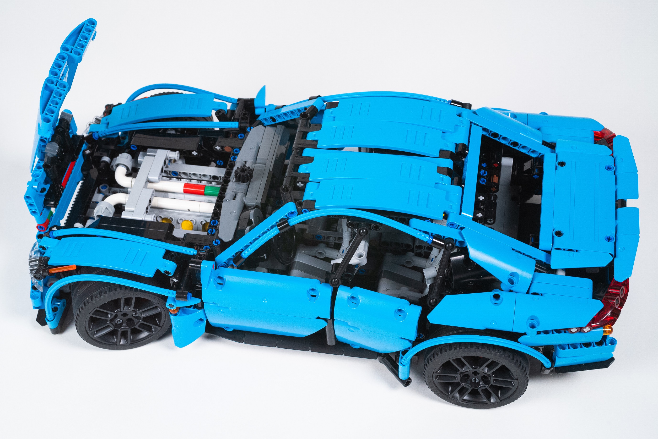
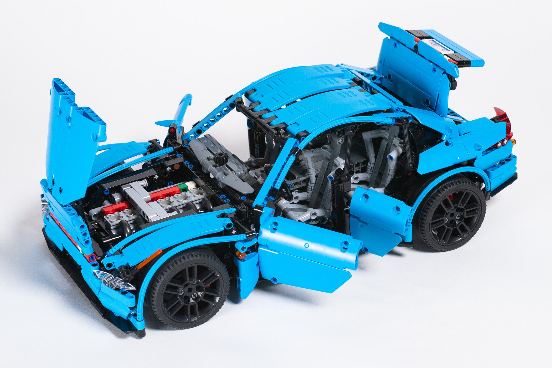
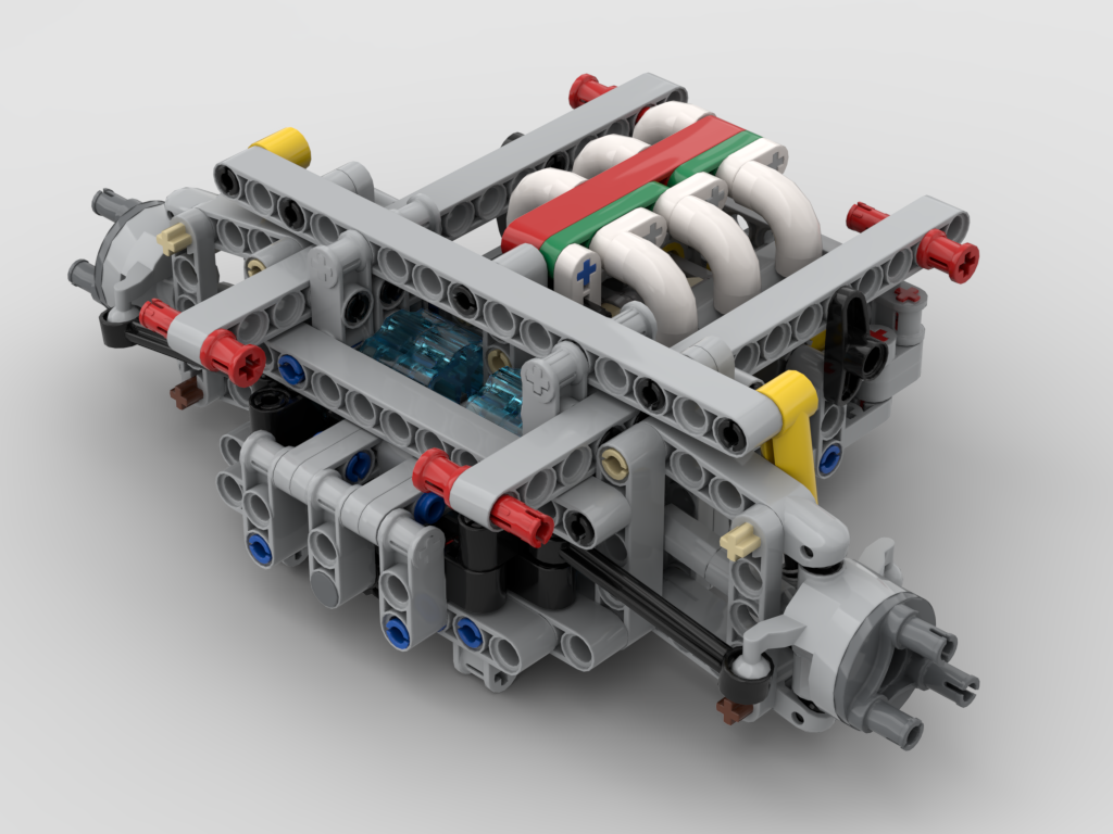
The engine tubs were a lot of fun and took less time than I thought they would. There are two tubs. The first, is built to support the front independent suspension and two different engine designs. The Straight Six is my favorite engine, so I wanted to make this options possible. The steering race for this module is placed far forward to allow for the I-6 to fit. In fact, the front of the engine is two studs from the front of the car. The V-8 fits well, and is placed behind the front axle centerline. The second engine tub features a fixed Flat 6 engine, and two fake electric motors; one for each side of the front axle. This unit is the hybrid and All Wheel Drive engine tub. Each tub attaches to either transmission module with six pins and one axle for steering. Drive connects by a 8 tooth gear off the engine.
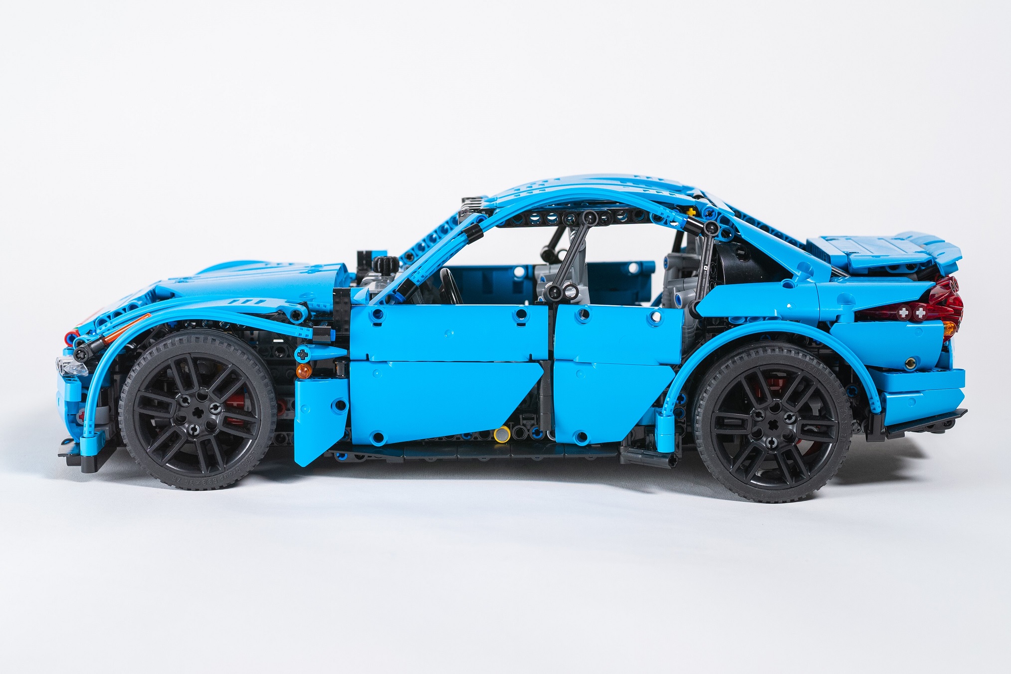
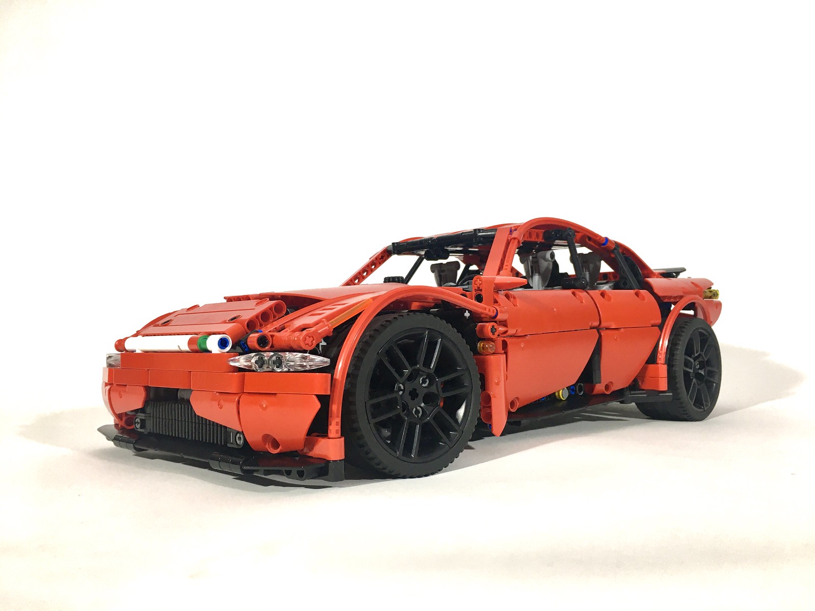
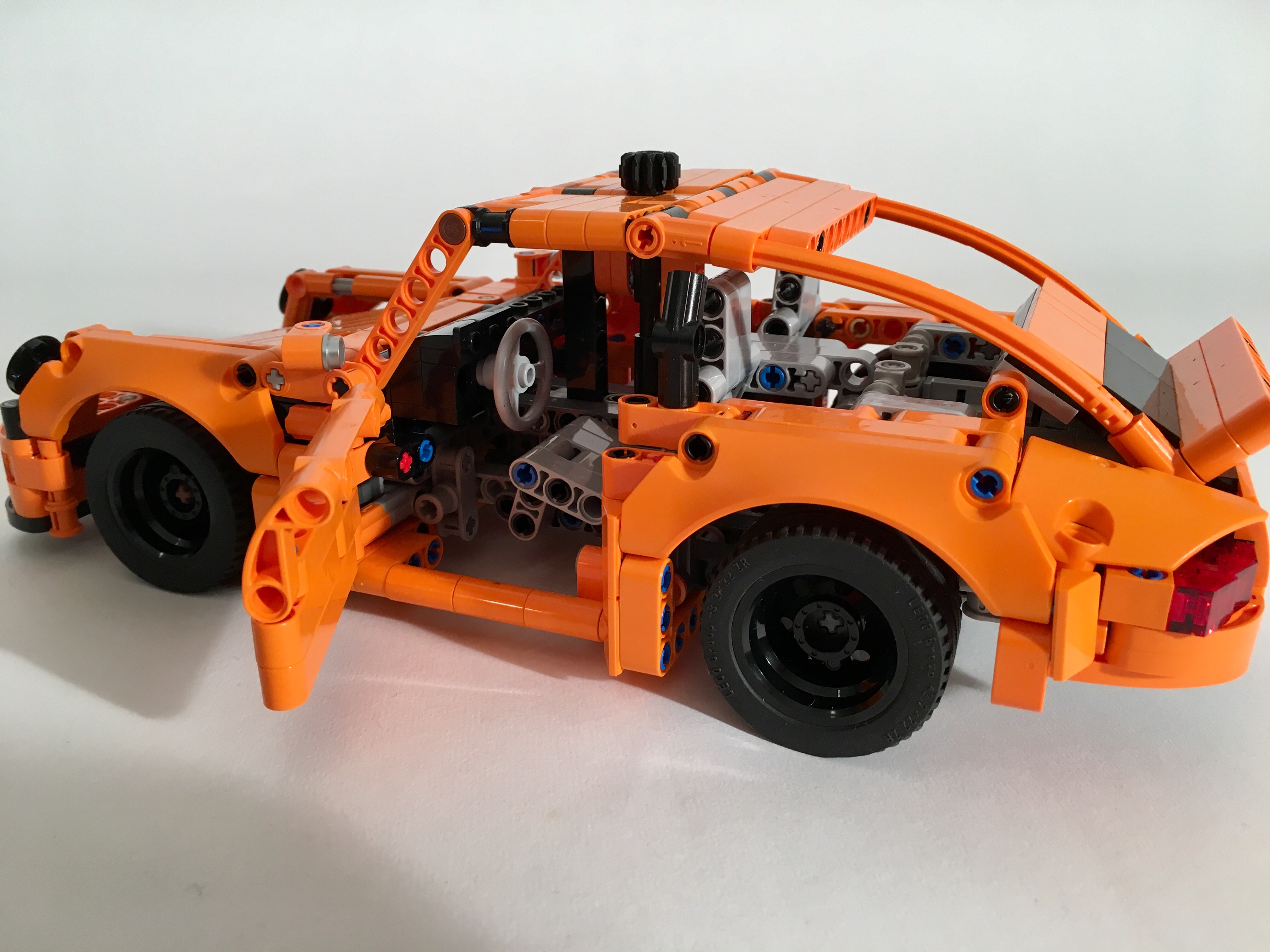
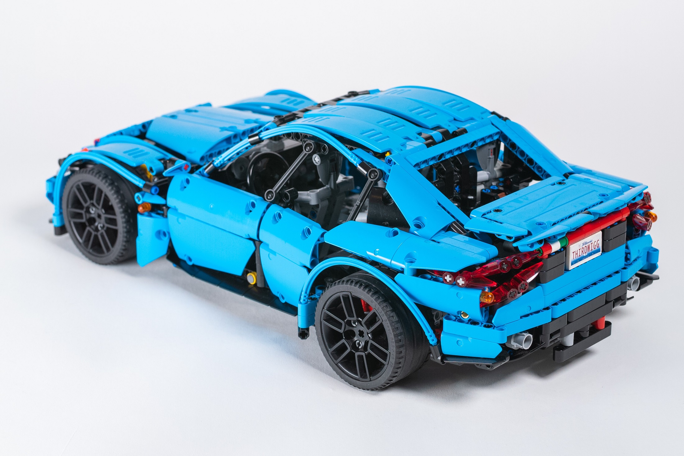
Then I built the floorpan. This simple build provides the floor to both the cabin and the underside of the car. It is connected at six points, four to the chassis, and two to the center of the body. These points stiffen the car, and connect it all together. The body took the most time as this is what most people would see. Early, I committed to the sides panels including the doors and the part just behind the front wheels, and the roofline. Otherwise everything else was fair game. The front bumper took some time in order of the two studs of space, but I was pleased with the design. Next I managed to get the A, B, and C pillars to look the way I wanted. The C pillar took some trial and error but finally got a shape that was fast looking without the coupelike lines that seems to be permitting sedan design these days.
The rear took the longest. It was at this point where my focus on the MOC was starting to wain. Over months I tinkered with different trunks, different lights, and different rear bumpers. Eventually, I got to where I am now which could be improved, but I was pleased enough to call it complete. I added a little spoiler, and the body was done.
After everthing was built set, I rebuilt the whole car. As I did, I checked fit and built a Bricklink Studio file. With each step I found improvements along the way, and learned how to make better instructions. The result was a car system that fit together well, and gave for an interesting build. Again, if you are interested in the detail, or building your own you may find the instructions here and here.
This was my most favorite build in a long time. If you are interested, the Dark Azure, Manual, AWD version is my preference. The integration of all the parts was fun to do, and the build, test, rebuild process that went through every stage was a case study in continuous improvement. Both transmission work flawlessly. The suspension is stiff and functions as they should for a car of roughly 2500 parts. The varied engines were a fun inclusion. The design of the car is sporty and keeps the lines and proportions of a traditional Rear Wheel Drive Executive Sedan: long hood, short deck, short front overhang. I hope you enjoyed the car, and if you build it, I hope you enjoy the build. I definitely did, and will do something similar in the future.
Until then, happy building.