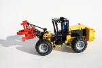
Bedford MWD


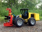
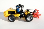
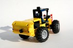
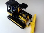
I have said it before, but my favorite things to build are Trial Trucks.  The combination of the driveline construction, forces on the truck, diversity of body style, and various propulsion systems offered by LEGO combine for a great building experience.  Because of this, I usually am building a Trial Truck, or have one built at all times.  But for some reason, this truck seemed to sit for a long time unfinished.  I struggle with deciding if a truck will be a model of something, or something fictional.  This decision is often made too late in the construction process.  After toying with a Daimler Scout body, I decided I needed to finish this project and the Bedford MWD body was chosen.

The full gallery may be seen here.

01

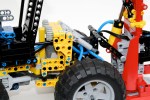
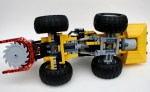
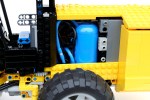
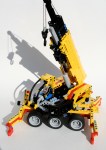
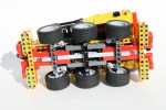
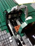
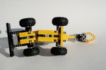
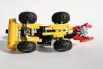
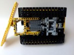
After some some experience with various designs, I decided to construct a truck around a simple locking differential idea I had recently designed.  Because I would need an extra IR Receiver for the locking function, I decided a simple two speed gearbox (1:6 and 1:10) could use the other IR channel.  I placed all the controls in the middle of the chassis.  The driveline and the steering axle would run through the middle.  On the left side was the Battery Box and the motor for the gear change, and on the right side was the XL drive motor, the gear box, and the motor for the locking differential mechanism.  The steering motor would hang out the back of the chassis over the rear pendular suspension unit.  Both axle were connected by my favorite linked suspension system.

zbedford

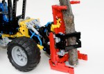
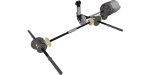
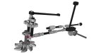
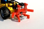
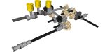
Each axle took a little bit of work.  I selected a simple design for the locking differential.  Basically, it is a 24 tooth differential placed directly next to a 24 tooth gear.  A pair of sliding 12 tooth double bevel gears slide back and forth one stud to connect only with the differential, or with both the differential and the neighboring gear locking out the differential.  After toying with some old flex cable, and some pneumatics, I figured I was making it too complicated.  I added a small pivot with a Small Technic Steering Arm, and connected it to a 9L link.  This way both axles could be connected, the suspension and lock could keep operating unaffected by each other, and it all could be controlled by a mini Linear Actuator.

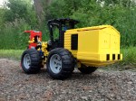
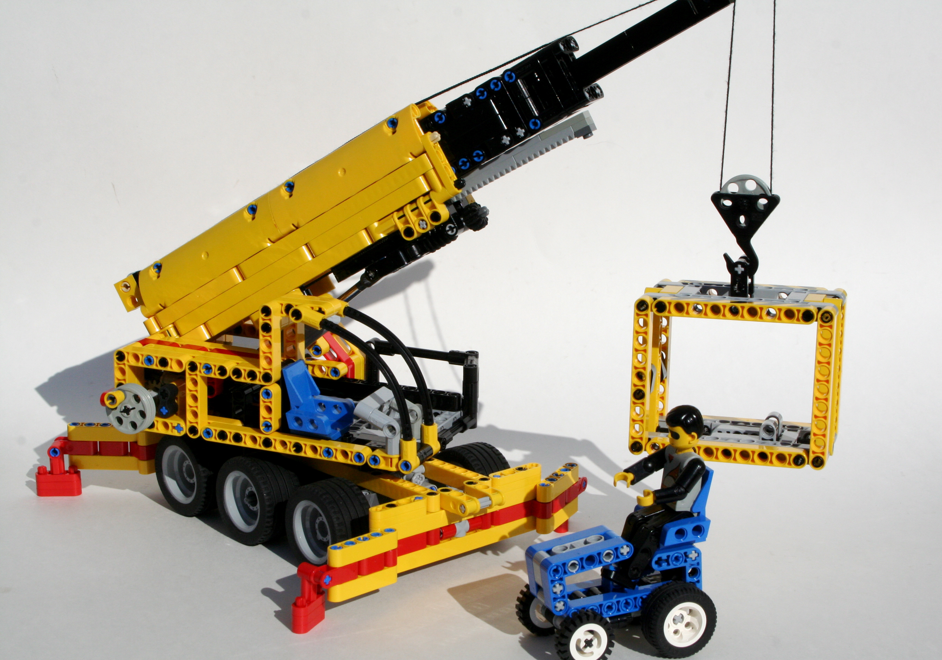
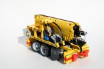
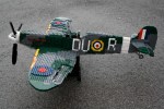
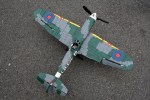
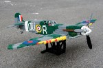
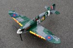
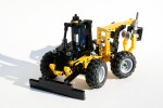
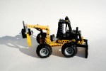
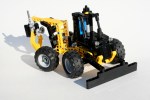
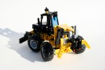
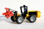
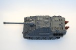
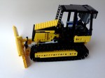
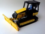
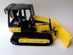
Initial tests were positive, so I then decided to figure out a body for the design.  I worked for too long on a Daimler Scout body.  I had the structure made, but the paneling was just not happening.  After sitting on the project for 5 months, I decided it was time to make something new.  The Bedford design worked well, and helped my get excited again in the project.

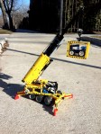
Now, once I got outside to drive the truck a glaring problem occurred.  The bevel connection in each axle that transmits the longitudinal drive forces to transversal drive forces kept slipping.  You can hear it in the video.  Because of this, it did not matter if it had locking differentials, or if it had a two speed gearbox, or if it had working suspension.  Anything could stop it.  I though about reworking the axles, but then, I have been working on this for 11 months, it was time to be done.  I’ll use the locking mechanism again.  That worked great.

Thanks for reading.

CAT 573C Feller


LEGO takes up space.  We all know this, and yet we still seem to try to cram as many working functions into a MOC as we can.  Sometimes it works out well.  Sometimes we have to scrap a few functions.  Other times, the functions are so dense you really cannot believe you got it to work.  This is the story of my wheeled feller.

The full Gallery may be found here. Instructions may be purchased for $5 USD.  Buy Now Button

CAT 573c Feller

I have been thinking about making a feller for about two years now.  It is a project I have never seen done before, with the exception of two tracked fellers (OK, and my other one).  Over this time, I have been planning, acquiring parts, and making plans, and over the last four months I have been building.  Nothing I have made has been so complicated or so dense.  There is no space left.

As I always do, I stared with the dimensions of the vehicle.  The schematics for the CAT 573C were easily available, so I stared with the chassis.  I knew space would be an issues, so the driveline had to be simple and compact.  The Power Functions XL motor would be geared down 3:1 and mounted just behind the rear axle.  A drive shaft would move through the steering pivot to the front axle.  The rear axle would have simple pendular suspension.  The steering would be completed by two linear actuators placed on either side of the pivot with a PF M motor on top.  Simple enough.

From here, things got complicated quickly.  The MOC would have four remaining functions.  The feller saw, the grapple arms, the feller tilt, and the feller lift.  Since trees are rather heavy, fellers are designed with as many of the system mechanics behind the rear axle.  As such, all of the functions I would add would need to be in the rear, as the front would not have any space.  I quickly learned this would not work.

Eventually, I found what would fit.  The IR Receivers would make up the rear bumper, and the battery box would be directly over them, off to the left.  Two PF Ms would be on the right and would drive two mini Linear Actuators.  These would move two pneumatic valves. These pneumatics would move the lift function and the grapple arms function.  An air tank would supply the pressure from a pneumatic pump placed on the driveline.  Another PF M would be placed over the front axle to give the feller head the tilt functions (it should be noted, 7 designs, and five weeks were spent on this feature alone).  The final PF M was in the feller head, and would drive the feller saw.

After packing, repacking, and packing again, all the features we set.  Then all the cabling and hosing were placed.  No easy task, as I was running out of space, and 25 or so hoses, and 10 cables take up a lot of room.  I added some comfort features to the cable, including a (half) chair and a roll cage.  And so Mr. Technic could get in, a little step.  Then a lot of paneling for the rear, including some access doors on the rear, and the model was done.  Here it is in action.

As you can see in the video, the MOC worked well, but some of the functions did not work as clean as I would have liked.  The drive and steering were fine, with an easy drivability.  There was a lot of mass in the back, so sometimes the torque from the drive motor would cause the back to tip.  The saw worked well enough, and for the most part so did the tilt, but the pneumatic lift struggled.  It was a little overloaded because the saw unit was too heavy.  The grapple arm worked well, but for both pneumatic rams were hard to control.  As always with LEGO pneumatics, they too often are off or on.

Until the next MOC, happy building.

Cargomaster Crane


We all have our favorite LEGO sets.  Then we also have sets that we think were pretty cool.  Set 6352 from 1991, the Cargomaster Crane was one of these sets for me.  It was a set simple set, it was perfect for a growing child.  Small, playable, yellow, and it could lift things.

Recently, I decided I wanted to make a little Technic crane.  I researched a number of designs, none of which really struck me as something I wanted to pursue.  I kept coming back to 6352. Why not make a crane like that?  Perfect.  I wanted it to be a nice homage to this classic set.  I was going to make is just like 6352.  Double the size, same shape, complete with container and tractor, and of course a driver.  The full gallery may be found here, and instructions can be found here.

6352 Technic

I stared with a simple frame built for the outriggers at both ends.  I knew I was not going to be able to add a more complex outrigger system at this scale that would reflect the original crane, so I made manual outrigigers just like the original.  I added two steering axles so the crane could drive to and from the site, then I placed a turntable right on top of the chassis.

As I started the superstructure, it become very clear very early, that having an offset crane boom like the original model, was not going to be a good idea.  My model was going to look off, and the balance of the offset boom was going to make stability, both for the superstructure, and the crane as a whole, a problem.  I knew the size of the boom, and decided to place it in the center of the crane.  I then placed the cabin, and set it up for the little technic figure.

The boom was relatively simple; two stage, and 23 studs long.  The outside was simple and straightforward, meant to be sturdy and strong.  The pivot was at the rear on top of the winch, and the elevation ram was connected forward under the front of the boom.  There was a simple worm gear under the front that would drive a set of gear racks, to drive the inner boom.  The inner boom would hold the final boom which was only a series of plates.  Each stage was connect by a two cables to make sure all the booms moved together in unison.  It worked well, even under load, as you can see in the video.

The model worked well, and had perfect balance.  The simple boom extension worked well, as did the winch.  The outriggers gave appropriate stability through all positions.  And it looked very similar to the original model, even with the little tractor.

Spitfire Mk IIa


I am not a very ambitious person.  Sure I made it through college and graduate school, and have managed to work well in job for a while now, but for me to do something challenging, takes a lot of convincing.  It doesn’t happen often.  This project was a little bigger than it should have been, and I got in over my head.  This is not the first time this has happened (1, 2).  The project was interesting enough for me to keep moving forward, even after six months.  I present my 1:12 scale Spitfire Mk IIa.  I hope you enjoy the work.

View the full gallery here, and the work in progress gallery here.  Flickr set is here, and full instructions may be downloaded here.

Spitfire 3/4

First, the whole reason I did this project was because of the excellent Baby Twin Otter of Cpt. Postma completed two years ago.  If you have not yet seen this creation, take a look at the above link.  When I first saw this model, I went home a made his variable pitch propeller   This was the first step to my Spitfire, though at the time I did not know it.

I chose to do the Mk IIa version Spitfire for a couple of reasons.  First, the model had to have a three blade prop, because I wanted to use Cpt. Postma’s design.  Spitfires stopped using a three blade prop somewhere in the middle of the MkV series.  Second, I wanted to model a eight gun variant, rather than the cannon variant because I think it has a cleaner look, and I love the red and yellow leading edges on the eight gun variants.  Finally, while it would have been great to do a early model Spitfire with the dark tan camouflage  adding both the dark green and dark tan would have been too expensive, and even more ambitious.  I found a number of pictures of a certain MkIIa with all the features I wanted.  I chose a Spitfire flown by Lt. Tomas Vybiral, who was a Czech pilot with the French Air Force.  The plane was Spitfire P8081 when he flew for the British in Squadron No. 312.  It had simple markings for me to recreate, a camouflage pattern I would be able to do (read afford), and I found some good documents to help my modeling.

Next came the internal planning.  The Spitfire would have working ailerons  flaps, rudder, and elevators (with correlating pilot controls), prop, prop pitch, V-12 engine, and retracting landing gear, all within the 1:12 scale.  Once I had the dimensions calculated, I started placing things in a simple “placeholder” model on my floor.  I constructed the engine, the propeller spinner, pedal/joystick assembly and placed them in the placeholder.  Then I made the placeholder 3D.

It took two months to get the rest of the internals all set.  The required moving various parts of the 3D placeholder, and adding additional parts.  The joystick is connected through various liftarms to the rear elevator, and by axles to the ailerons   The pedals connected though a shaft to the rear rudder.  You can see the gears on the rudder.  The flaps have a simple lever in bottom left side of the cockpit.

The rest of the functions are controlled via Power Functions.  The small 8878 battery box is placed behind the cockpit, as is the IR receiver.  A PF M is housed under the V-12 and drives four mini linear actuators for the landing gear.  It is strong and simple, and works well.  It does not have the correct Spitfire landing gear geometry, but if someone can figure out a way to do it at this scale…well, I can’t figure it out.  A second PF M is used to power the propeller   It is placed directly behind the V-12.  Finally, a third PF M is placed behind the V-12, and works through a system of gears to power two mini linear actuators to move the pitch of the prop.  It’s messy inside, but it has everything I wanted.

After the internals, I had no idea how hard the rest of the Spitfire would be.  LEGO, you need to make more parts in Dark Green.  I know how selfish that sounds, but it would have been more helpful.  Thank to some newer sets, like the 10226 Sopwith Camel, and the  21016 Sungnyemun, it made it much more possible, but still limited me in many places.  I spent the next four months acquiring parts, and placing small plates over the rest of the plane.  With some help on the roundels from Dieterr89, it eventually came together.   The bodywork took a long time.  Too long.  And the lack of some parts in Dark Green forced me to make some concessions.  The canopy frame should be all Dark Green, but it was not going to happen with what is available.  The camouflage is not as clean as I would have liked, and there are some abrupt steps where some plate limitations made the transition for one part to another not smooth enough, such as on the rear fuselage.  Also, try as I might, I could not get the leading edge of the wing to be perfect.  The dihedral did not help either, nor did the yellow leading edge.  Also, the gaps between the control surfaces and the fixed part of the wing and stabilizer was more than I would have liked.  But this has happened before.

I am please with how it turned out, but there are some parts that I wish would be better.  I never seem to remember this when I start a project in this scale, but free moving functions just do not operate well as you hope when you keep adding parts.  The control surfaces work, but they could be smoother and lighter.  The powered functions worked flawlessly. I was very please with the way the markings turned out.  They are not as flush with the plane as painting would cause you to believe, but they make the Spitfire clearly identifiable.

My father would always tell me “never say never,” but it may be a long time before I do another large plane.  But I guess I said that back in 2008.

I hope you enjoy.  Thanks for reading.

Mini Skidder


My Mini Feller started after I made this MOC.  I wanted to do a small little project, and I wanted to do something fun and simple, and I thought the Mini Feller would be a great partner to the Mini Skidder.  The skidder is a simple design, that uses simple construction techniques, unlike the Feller.  Also, you can build your own.  Feel free to check out the instructions here.

I started with the rear grabber.  I added a simple worm gear to 8z connection that moved one of the arms, and connected it to the other arm with a 16z to 16z connection.  The axle that connected to the worm gear would exit out of the top of the grabber and allow for movement with your hand.  I attached it to an arm that would attach to the MOC.  The arm would be connected by two arms on each side of different lengths, so the grabber would move in an arc, and connected to the chassis.  On the chassis I connected the rear arm to a 24z gear, and placed a worm gear above it.

I connected the rear part of the skidder to the front part with the new small turntable.  This allowed for simple gear connection with a 20z gear to the Hand-Of-God steering.  This worked well, and kept the model simple.  Just in front of the steering mechanism, I added another 24z gear for the plow.  Taking a cue from set 8069, I set the worm gear vertically, and connected it to the exhaust stack; simple and pretty.  I then filled in the space.  A simple body was added, as was the plow, and wheels, though not in the cleanest of ways.

It was fun little design with simple solutions for the functions.  It’s not as complicated or compromised as my Feller, but still a playable MOC.  Also, its easier to build should you feel the need.

The full gallery may be found here.

Thanks for reading.

Mini Feller


Building with Lego is a continuous formation of compromise.  While my ideal of what my Mini Feller would include was significant, what I could actually accomplish was a compromise of space, function, realism, and frankly the amount of frustration I was willing to tolerate.  So while the final result is a watered down version of what I would have liked, it was the result of me compromising amidst the situation.

Instructions can be found here.

I wanted to make a small model go with my Mini Skidder.  The MOC had to be the same scale, have a decent level of fuctions, and work with my Skidder.  A feller seemed like a good option.  As I looked at what function this MOC would have, I ambitiously stated it must have a working blade, working steering, working grapper, and a working tilt function.  All these functions would be controllable on the back or on top of the cab.

The steering was simple enough.  I added a small turntable at the bottom of the chassis to give the frame some support.  The HOG steering axle would come out at the top of the cab, and join the front and the rear with a small link arm.  Simple enough.  Likewise, I added a differential in the rear part of the chassis, geared up the rotation, sent it though a couple of universal joints to the front of the Feller, connected it through a pair of 12z bevel gears, and attached a saw blade.  Again, simple enough I had steering and a working blade.

It got complicated as I tried to add the arm features.  The lifting of the arm would be done with a 8z gear with a worm gear.  Because there was a driveshaft to the front blade, the 8z gear needed to be placed on the axis of the arm, but out of the way of the driveshaft.  The required a 1 stud offset that also needed to be directed back through the steering axis to the rear of the Feller.  I used a CV joint to allow the axle to slip as the feller would steer.

The tilt feature would require a parallel control that would allow the elevation happen while keeping the feller blade parallel to the ground.  This would require another 8z worm gear connection at the lower rear pivot point of the arms.  I was running out of space.  Of the 7 studs to work with, one was used for the universal joint, one was used for the lifting gear, one for the mounting liftarm, and one for the lifting arm.  I could not add another worm gear system, while being able to actually lift the feller blade.  Additionally, adding a link for the gathering arms would also have to work through this pivot point if I wanted to isolate the movement from the lifting and tilting feature.  I had to give.  A compromise was necessary.  I felt the stability of the feller blade had to be paramount, so I added another support arm.  I also felt gathering arms must remain as they are essential to a feller.  Sorry, but the tilt feature got the ax.  It was the correct decision, but it still tasted a little sour.

It was a great little MOC, and I had a good time creating it.  I hope you enjoy building your own.  The full gallery can be viewed here and the instructions can be viewed here.

Thanks for reading.

Flat 6


Every once and a while I get picked up by another LEGO blog. I am honored when it happens as it show others value my work. However, it seems to happen when I lease expect it, and in creations I find fun, rather than significant.  Thank you none the less.

Thanks to the Lego Car Blog for posting my Dune Buggy and my Zil 132, and The Brothers Brick for Posting my Rumble Bee.  Spreading thirdwigg is deeply appreciated.

thelegocarblogger's avatarThe Lego Car Blog

This monster dune buggy was unearthed by the Elves on MOCpages. K Wigboldy has included steering, all round independent suspension and, best of all, a huge six cylinder engine hanging out the back.

View original post

Sd. Kfz. 173 Jagdpanther Late Version


For some of you, this may come as no surprise, but I like to build with more than only Technic.  I find a lot of enjoyment building with Technic, but as a child I had more fun with the bricks.  My resources (and bricklink.com) now allow me to build some of the things I never could at that time.  To this day I still like making tanks, so I present to you a model of the Sd. Kfz. 173 Jagdpanther.  This is still one of my favorite tanks: simple lines, great stance, decent performance, and for my purposes, able to be made in LEGO.

Building instructions may be found here.

While I love building tanks, I don’t build them often.  Posting a tank to the LEGO community online is asking for trouble.  There are a lot of builders like me who like to build tanks, so it is hard to make a tank that doesn’t take some influence from someone else.  While the design is mine, there are a lot of ideas from others that have influenced this design.  Feel free to take a look as some of the ideas in this gallery.  Thanks to the various builders.

I have some more Technic models in the queue, so until then, enjoy this break from normal.

The full gallery may be viewed here.  Thanks for reading.

International FTTS


It has been a little quiet in Thirdwiggville for the last month.  I have been working on a project that is taking a lot of time and resources, so my posts have slowed, even though my building has not.  But just wait, it’s going to be awesome.

Last summer I wanted to do another Trial Truck that would utilized some features I have never used before.  I wanted something complicated to see how it would work.  I wanted a model that would use four wheels steering, independent suspension, and have a simple two speed gearbox while being low to the ground.  After spending some time at the Chicago Autoshow, I saw a FTTS concept, so I thought this would be a great vehicle to model for this next truck.

This model would be built around an independent suspension.  After seeing it used so effectively in a truck by ATRX, I wanted to give it a try.  Each of the four wheels would use a simple double a-arm set-up with a wheel mount attached at the outside.  The wheel mount would house the portal axle and connect the steering linkage.  After a couple of different designs, I also decided the wheel mount would also connect the the shock absorbers.  This was a little unorthodox, as most independent designs mount the shock absorbers directly from the frame to the a-arms.  I did this for two reasons.  First, the model would be heavy, and I could not get the support I needed when the shocks were connected to the a-arms.  Second, and most importantly, I noticed too much suspension flex when the shocks were mounted to the a-arms.  The force applied to the wheel would go up the wheel, to the wheel mount, through the pivot, halfway down the lower a-arm to the shock.  LEGO is relatively stiff, but all these steps complied too much flex.  I would not have it.  I mounted the shocks on the wheel mount, and created a simple MacPherson strut set-up.  This worked well, as it allowed for full steering movement, long suspension travel, and adequate support of the truck.

The front and rear suspension axles both had a PF-M motor driving the steering.  Each were on independent PF channels connected to a single 8878 Battery Box to allow for individual steering, crab steering, and to solve steering drift commonly problematic with four wheels steering vehicles.  Both axles were connected with dual drive shafts running the length of the truck.  One drive shaft would then connect through a simple two speed gearbox to the PF-XL motor.  The final gearing was 1:6.2 and 1:10 for the truck.  This gave the truck sufficient top speed, with an effective crawler gear.  The Battery Box used for the drive motor and the gear shift motor was placed directly behind the front suspension, and in front of the drive motor.  This placement was perfect for stability.  It helped give great traction to the front wheels, kept the center of mass low and to the center with a slight forward bias.

I then finalized the model with a simple removable body built on a Technic frame.  While the hood was little high, and the rear body a little too short, it looked pretty close to the rear FTTS.  Fans seems to like the look, as it is still one of my more popular model.  See the full gallery here and the Work in Progress gallery here.

The model was a lot of fun to drive, and due to its squat design, it was very well planted.  The truck did not want to role over.  I think it could have used a little more suspension travel, and having four wheel steering was crucial to give it some maneuverability that was lost due to the suspension design.  The gearbox was flawless.  The truck did have some trouble skipping gears at the portal axle.  It seemed to happen when a single wheel was over-stressed as the driveshaft could have used stronger bracing in each suspension unit.  This placed a lot of strain on the particular wheel.  So would I do the independent suspension again.  Maybe, but it would need some strengthening and redesign.  Maybe it’s time for another truck like this.

Thanks for reading.  Something big is coming.

CAT D5K


Construction equipment was pretty much designed for LEGO Technic.  I learned this while designing my MB Axor Refuse Truck.  Yellow bricks are pretty popular and accessible, the equipment usually has many functions which can be replicated, and working models with power functions can be made to reenact various construction projects for great playablility.  After finally getting some large track links, I figured it was time for me to do a bulldozer.

I wanted to model the CAT D5K for a couple of reasons.  First, it used a two wheel track for each side rather than a three wheel track for each side.  Second, I wanted to do something by CAT.  Third, I decided on the D5K because for dozers of this size I think it looked the best due to its stance and overall balance.  Plus, when I started looking at the scale of the dozer I was to model, I learned the D5K would work best with the parts needed such as the tracks and blade, and work with the internal space allowed.

The base D5K really only has three functions: drive, blade lift, and blade angle.  I had no intention to add a ripper, because, frankly, I ran out of space.  Space became an issue very early.  I had 9 studs to work with between the tracks, and I needed to add four motors, a dummy motor, a battery box, and two receivers, all while retaining the appropriate look.  All the gearing had to be compact, and the linear actuators needed to be placed efficiently.  The real D5K has a manual adjustment for the blade pitch, but all of my designs left something more to be desired, so I took it out.

Both tracks would have their own motor, and I wanted to link them to a dummy engine, which required a differential.  I connected the motors directly to a worm gear which drove a 8z gear.  This gear was on the axle for the rear drive wheel, and connected on the other end to a differential which connected both drive wheels.  This differential functioned as a power take off for the dummy motor in the front of the bulldozer.

Two more motors were placed under the dummy motor.  One connected though a 12z/20z gear reduction for the blade angle.  It proved difficult to supply power for the blade angle function through the blade tilt pivot without taking up too much space.  The second motor was used to adjust the blade height.  After a simple reduction, two mini linear actuators were used to move the blade up and down.  It worked well, and was plenty strong.

I added the battery box under the driver’s seat, and placed the two IR receivers in the top of the cab.  It was not optimal aesthetically, but it seemed to work well for control.  And again, I just ran out of space.  I worked on the body, gave the model a working hood, and built a cabin.

The model worked well, but building with tracks is always a little bit frustrating.  Like it or not, LEGO plastic will never be fully smooth, and this is compounded with the track system.  Also, I found that the dummy motor would lose its connection to the drive wheels, as the axles connecting to the differential would slip out every once and a while.  This seems to be a commom problem with Technic builders, so we will see if the new axles will help.  I liked the size of this model, and it had a good amount of functions.  Now I need to use the tracks for something else.

Maybe another tank.

The full gallery may be found here.