Power Functions 4×4 8081


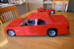
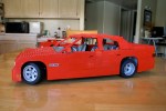
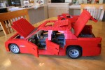
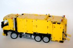
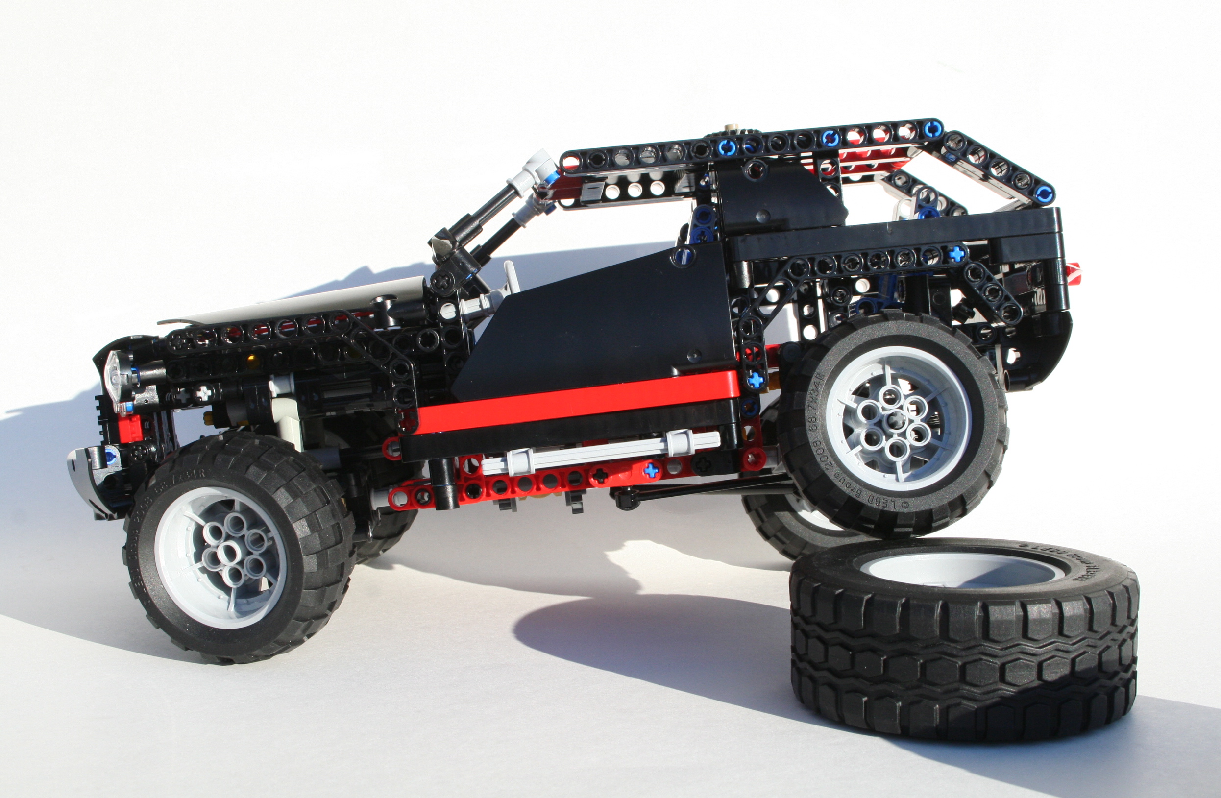
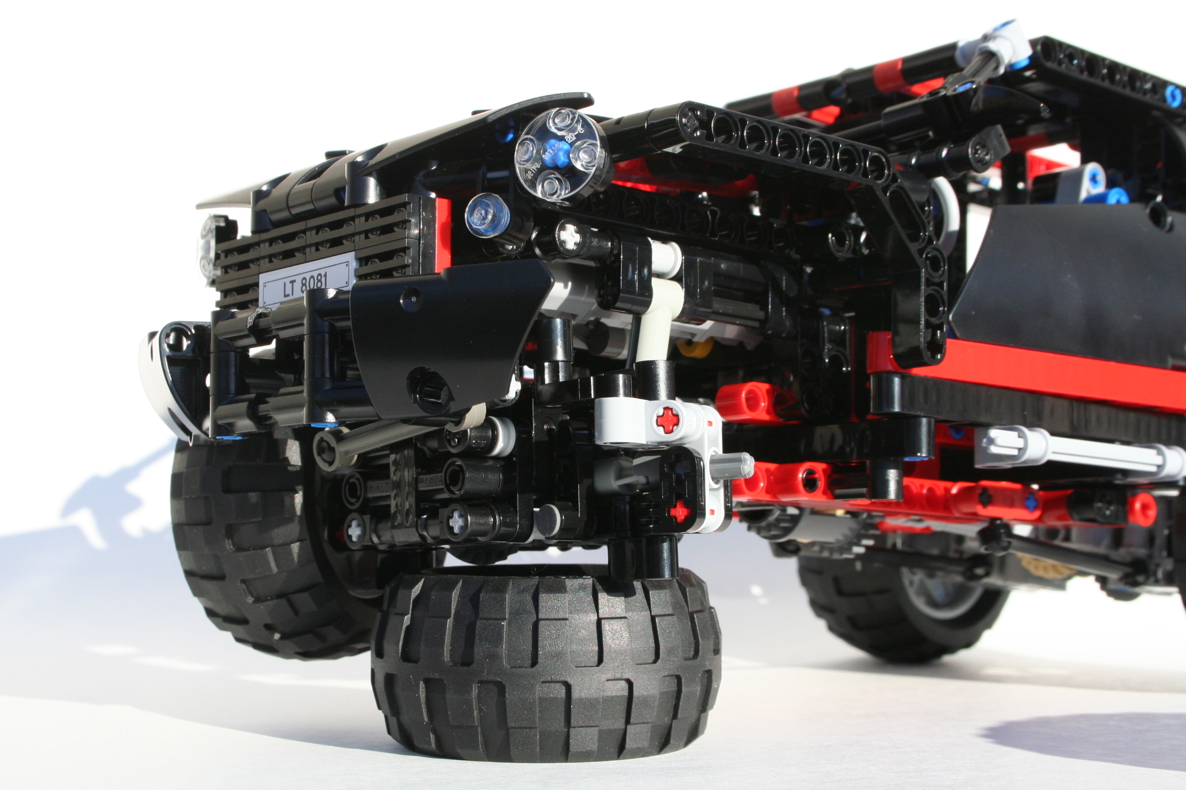
For most LEGO enthusists, when they purchased the set 8081, they quickly modified the set with a Power Functions drivetrain.  It makes sense.  LEGO models are a little more exciting when they are motorized.  But I guess I went a little backwards.  I wanted to do the fun stuff first, and make the most complicated and compact drivetrain I could make.  I posted the instructions here, and they can also be viewed on Rebrickable.com.

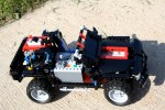
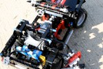
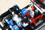
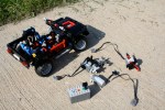
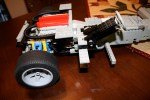
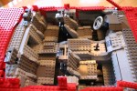
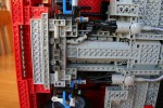
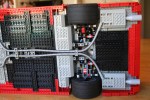
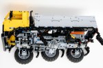
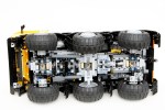
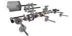
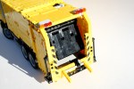
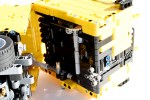
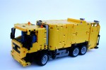
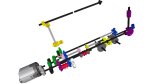
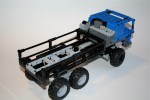
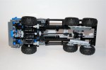
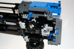
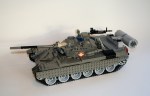
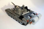
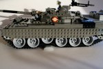
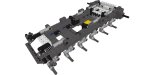
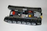
But the comments kept coming from people who wanted to see my model motorized.  So I thought it might be a fun addition.  I added a two PF M motors, a 8878 Battary Box, and an IR receiver.  I tried to keep the modifications simple, so I could easily add the motors to the MOD, and take the system out if I wanted to.  The drive motor was placed on a simple mount that connected to the frame.  The power was fed thought a 8z gear to a 24z gear which then connected directly to the V8 driveshaft.  The driveline was unchanged from the V8 down.  The steering motor was mounted laterally in front of the rear seats.  A 20z double bevel gear drove a 16z gear, then a worm gear moved the final 8z gear which was mounted on the existing HOG steering axle.  I removed the passanger seat which is where I placed the battary box, and created a simple mount for the IR receiver.  The added weight required a new shock absorber, so I added that as well.

The model worked alright.  The drivetrain did well to handle the new power, and I could easily control the Crusier.  The steering motor was a little too powerful for the upside down facing steering rack.  It skipped a little under load, which was a problem over rougher terrain.  The drive motor was a little taxed, so a PF XL would have done a little better.  I guess I could add that, but I am ready to move on to my next model.  Stay tuned.

The full gallery may be found here.

Red Sedan


When I got out of college, I started getting back into LEGO; the end of my “dark ages.”  I wanted to make a large supercar, just like everyone else.  But after my first attempt, there were a couple of things I wanted to improve, and the first car did not really look right.  OK, so what needed to change?  I needed to stretch the car, and make the stance a little better, add some features, and make it as real as possible.

See full gallery here.

I used the dementions of the 2005 BMW 5 series as my template.  From these demensions I used the F1 Racer wheels and tires to set the scale, then I determined the wheelbase, got the width, and I went to work.  I first made the rear suspension unit, and then the dual cam V-8.  Then I linked the two with a 4 speed transmission, and a long driveshaft and added a simple parking brake.  It took a little work, but I then added the front suspensions.  I have found it best to use technic beams to mount the front suspension. The A-arms are then attached to this structure, with the shock absorbers placed on this structure and braced with liftarms.  I then connected this directly to the front of the V-8, and connected it to the rest of the chassis with a simple frame.  I used the old steering mounts of the old 8865 supercar, and connected them to the steering wheel through an upside down mounted steering rack.  Of note, the car was going to be big and heavy.  I had to find a way to get two hard shock absorbers at each wheel which limited the suspensions options I had.  In addition, I added a front and rear sway bar, which took a little more space, but it worked.

Then the body.  I worked first on the doors, and the front bumper.  I used a dual pivot design for the doors so they would open even though bricks do not work well with pivots.  Then I did the front and rear quarterpanels, and set the rear bumper in such a way that a full size spare tire would fit.  I then worked on the interior.  I designed a simple tilt steering using a worm gear, and a universal joint.  I made sure to use the great front seat design by Pixsrv, added a rear bench seat, funished the trunk and added all the little compartments in the center console and glovebox.

I finished with rest of the body work.  The roof had a sun roof, and the trunk would have a damped shock to hold open the  trunklid, and added small details and some mirrors.  It was big, and it was done.  I was pleased with my first large car.  It still my most popular on Brickshelf.com.

All in all it was a great experience to learn about how to make a large car, and all the challenges that go with that.  Frankly, since this design, most of my cars have been a little smaller, as it makes the suspension and steering work a little bigger.  Lessons learned.

The full gallery may be found here.

Zil 132


A couple of months ago I was struck by a new design by Waler.  It was refreshing to see a well made Trial Truck based on something a little different.  I wanted to make a model of my own.  Thanks to him for the inspiration, and for the great ideas on the cab and the fenders.

From the beginning I knew this truck was not going to be a serious off road contender, but I wanted to redesign the whole drivetrain.  I decided to go with a pendular suspension for the first and second axle and a trailing live axle for the third axle.  All three axles would have a differential and a a set of portal axles.  The first and the third axle would also have steering linked together.  As is often the case with my trucks, I had the pendular axles held by a turntable with the steering function passed through the turntable by use of a differential.  The second axle was held by a turntable in the front, and the steering differential passed through to provide steering to the final axle.  The drive function powered all three axles and would connect to the transmission and motor in between the first and second axle.

The third axle was a suspended live axle that had a trailing setup created with the new 8110 pieces.  This would allow for rotational and vertical articulation while connecting the drive shaft and giving space to the steering function above.  The steering shaft would allow for movement via a CV joint.  The Power Functions M steering motor was placed in the rear, and used a simple 1:9 reduction.

A Power Functions XL was used for the drive funtion and was placed between the front two seats.  The motor was mounted on a sliding assembly for the gearbox function, much like the design pioneered by ATRX.  I used my three speed changeover design to move the motor through three gears, for a final ration of 1:7.5, 1:4.7, and 1:3.  The gearshift worked perfectly.  While the drivetrain was a little complicated, the gearing was rather simple.  The battery boxes were place above the second axle side by side.  This kept the weight centered, and as low as I could get it.

Finally I added a cabin and a cargo area.  The cabin was straight from Waler’s design, as was much of the fender area.  I used technic panels to create the cargo area, which also gave me a space to place the two IR receivers.  This also hid the two battery boxes, and the wiring, and generally cleaned up the truck.  I created two small doors in the top to assist with picking up the ZIL.  I was done.

Over mostly level ground the ZIL was one of my better designs.  The differentials and steering worked flawlessly to make the ZIL drive easily.  The gearbox worked well and eased the drivetrain over slight irregularities.  But once the  pavement turned to dirt the ZIL struggled a little more.  It was not designed to have too much suspension travel, and this showed.  It struggled on some of the bigger bumps, as the tires would scrape the wheel-wells.  Overall, I was pleased with the design, and was happy with the way it turned out.  It looked great, it was fun to build, and it was a blast to drive.

The full gallery can be viewed here.  Also, a big thank you to The Lego Car Blog for posting this model on their blog.

Mercedes Benz Axor Refuse


I am a big fan of garbage trucks.  For some reason I find the combination of a smaller truck,with many features all with a complicated compaction device is a great basis for a complicated LEGO Technic model.  Plus, trucks are fun.

The hardest part was going to be the rear compaction device, so that is where I started.  I decided to use a Geesink Norba design as it would give me the largest opening for the trash in the rear because the mechanicals would be on the bottom on and the top of the opening.  13 studs wide is not much space.  In addition, this would allow me to have the rear hopper pivot up to let the trash out when it was full.  I would need to have three functions going though the pivoting hopper.  One at the pivot, and two connecting at the base when the hopper was closed.

The dumpster lift would be driven through a knob gear when the hopper was closed on the bottom.  The compation device would be operated with a gear on the bottom and a mini linear actuator on the top.  This mini linear actuator would also function as the opener for the rear compactor.  All the motors would be housed on the bottom, with one motor placed next to thebattery box.  The extractor would be operated by another mini linear actuator using a scissors mechanism to move the ejector plate.

The chassis was constructed with a PF XL in front of the steering axle.  The motor would power both the drive, and the extractor changed by a changeover.  The steering motor is placed on the right of the truck.  On the left, another PF M motor powers both the dumpster lift and the lower hopper compaction device.  All power came from a 8878 rechargeable battery box, through two PF IR receivers, and powered four motors: One XL for drive and the extraction plate, one M for steering, one M for the dumpster lift and lower compaction, and one M for upper extraction and hopper opening.

The model worked well, particularly steering and the drive.  However the extraction and the hopper opening was a little less reliable.  The hopper was too heavy for a single mini linear actuator, and the compaction device was not stiff enough.  It happened to get caught on some of the internal edges on the inside of the hopper.  The next garbage truck will need to be built a little more sturdy.

The full gallery may be seen here.

JCB 930 Forklift


It was time for me to to make something that was a little smaller with a lot of functions.  I kept driving by a JCB forklift on the way to work, and I thought I could make that.  I wanted manual functions, including a working fork tilt and dual stage lift, working steering and drive, and a yellow bodywork.

I always start with the hardest part of a model.  For this model, that was the fork.  I wanted to use a dual stage lift as to get the forks to a substantial height.  This design would require a chain that would wrap over a moving frame, and connect on one side to the forks, and on the other side to the body.  The moving frame would be moved by a screw, thereby lifting the forks.  I used a number of worm gears on two 12l axles, connected through the bottom to move the moving frame.  This setup allowed for a pivot point, and a lifting mecanism that would function much like the real JCB 930.  The moving frame consisted of two rows of liftarms, and the forks tied everything together between the moving frame and the worm gears.  A chain went up and over the full assembly to work move the forks as the moving frame was lifted.  It works like this.

I then worked on the driveline.  I added a 3 cylinder motor in the rear, driven by the front wheels, working to keep the functions out of the way of the fork mechanism.  I added a steering axle on the rear, and gave it a pendular suspension setup.  This allowed for some stability on uneven ground, while keeping the front wheels planted for the load as it had no suspension.

I then built the body after the JCB 930, and as I did, I added a tilt freature to the fork.  This feature did not work too well, but it gave me the ability to adjust the pitch of the forks, which we a design requirement.  It was not too stable.  After a little work to the body, and a HOG steering link out the top of the cab, the model was done.

The model worked well, particularly the lift feature.  I was a little disappointed with the tilt feature, as it was a little too wobbly. The drivetrain worked well, and the steering allowed for tight corners.  The suspension give good stability, and offered a little bit of off-road prowess.

The full gallery is here.

4×4 8081


Truthfully, I was excited about set 8081 when it was first announced.  I liked the size.  I liked the coloring. I liked the stance.  But mostly I liked the potential.  Most of the Technic community dismissed the 8081 because of its watered down functions, but I was interested in making some changes to see if I could make the Cruiser Extreme.

The full gallery can be found here, and instructions here.

Image

I first added a V-8.  There was plenty of room, and after seeing a great modification from Efferman, I had some ideas.  It was a simple addition.

Image

Next was the drivetrain.  This was a little more complicated.  I wanted to make it four wheel drive, and I wanted to make sure there were three differentials.  I rebuilt the rear axle, so It would have a more active setup.  I put in longer shocks, and added a Panhard rod, and two stabilizing links.  It worked well.  The front axle was more challenging.  The new CV joints made the project a little easier.  Once I had the differential place, I had to fit everything around it.  The steering rack was placed upside down, and was connected directly to the existing steering link in the original 8081.  Then I added a Panhard rod on the front of the axle, and rebuild the front bumper, and everything was set.

ImageImageImage

Instructions can be found at Rebrickable.com or here.

Full gallery is here.

I also created a motorized version after a number of requests.  You may see the gallery for that MOD here.

LMTV Mini Truck Trial


As I start this new blog, I thought it may be helpful to post some of my older models to show what I have done, and give a little history to my designs.  In the midst of getting into Trial Trucks, I decided it was time to make a new smaller truck.  I designed a mini truck, to test my abilities with smaller functions based on the Oshkosh LMTV military truck, and to take my mind off the design that was taking most of my time.

I chose the six wheel truck as it would make the suspension of the truck a little more simple than other designs.  The rear axles would be tied together on each side, with a pivot point in between each wheel; one for each side.  A single axle would connect both sides through the dual pivot points, and would be powered by a worm gear directly from the drive motor.  This set-up did not require any additional suspension components, and this would allow the front axle to use an unsuspended pendular set up.  The PF M drive motor was placed above the rear wheels and drove an axle that would go to both the front and rear axles.

Like the rear, the front axle would use a worm gear directly from the motor to drive the wheels.  From the worm gear, a 8z gear was used to drive two 12z double bevel gears for each wheel.  Both 12z gears would drive two more 12z double bevel gears to which allowed for drive through the steering axis.  A simple link connected the two steering wheels, and used a rack and pinion setup to transmit the steering function.  It worked well, and allowed the steering motor to slip at steering lock.  A PF M steering motor was placed above the front axle in the cabin.

I created a small bed, and cabin for the truck and decided to build the truck in blue.  As I was browsing through my Brickshelf folder, I noticed I had too many red vehicles, so something blue would be good.  I placed the 8878 battery box, and PF receiver between the cab and the bed.  This allowed for proper center of mass, and gave me a fully functioning bed.

The model worked well.  For such a small vehicle, it took a lot to stop the truck, in part because of the worm gears.  The steering worked well, but the turning radius was limited, due to the poor steering lock.  I was a fun model, and it is still one of my more popular projects on Flickr.  See the full brickshelf gallery for a more complete view.

T-72


As a child I always wanted a model of the Russian T-72, so I decided to create a version of the tank out of LEGO bricks.  As is often the case, the model started with wheels.  This determined the scale, and from there, I was able to determine the rest of the tank dimensions.  This gave me very little room for all the functions of the tank.

Instructions are available for $5 USD.  Buy Now Button

Model of the popular Russian T-72. View the full gallery here.

The tank includes independent suspension on all 12 of the drive wheels.  6 are suspended with 6.5 length shock absorbers, 4 are suspended with rubber connectors, and the final two are not suspended, but move freely with the track.  The tracks are driven from the rear by two longitudinally mounted PF M motors.   These are connected 1:1, through double bevel gears to the 24z sprockets.  The battery box is place in the front of the tank, with the IR receivers placed over the drive motors.  The final PF M is mounted vertically in the turntable, to rotate the turret.  It could use another reduction, as the rotation is a little quick as you can see below.

I was pleased with the way this model turned out.  While the functions work alright, the aesthetics of the tank represented the original well.

The full gallery may be found here.