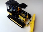
CAT 573C Feller


LEGO takes up space.  We all know this, and yet we still seem to try to cram as many working functions into a MOC as we can.  Sometimes it works out well.  Sometimes we have to scrap a few functions.  Other times, the functions are so dense you really cannot believe you got it to work.  This is the story of my wheeled feller.

The full Gallery may be found here. Instructions may be purchased for $5 USD.  Buy Now Button

CAT 573c Feller

I have been thinking about making a feller for about two years now.  It is a project I have never seen done before, with the exception of two tracked fellers (OK, and my other one).  Over this time, I have been planning, acquiring parts, and making plans, and over the last four months I have been building.  Nothing I have made has been so complicated or so dense.  There is no space left.

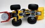
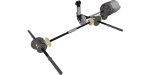
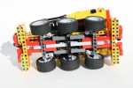
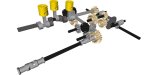
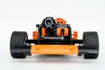
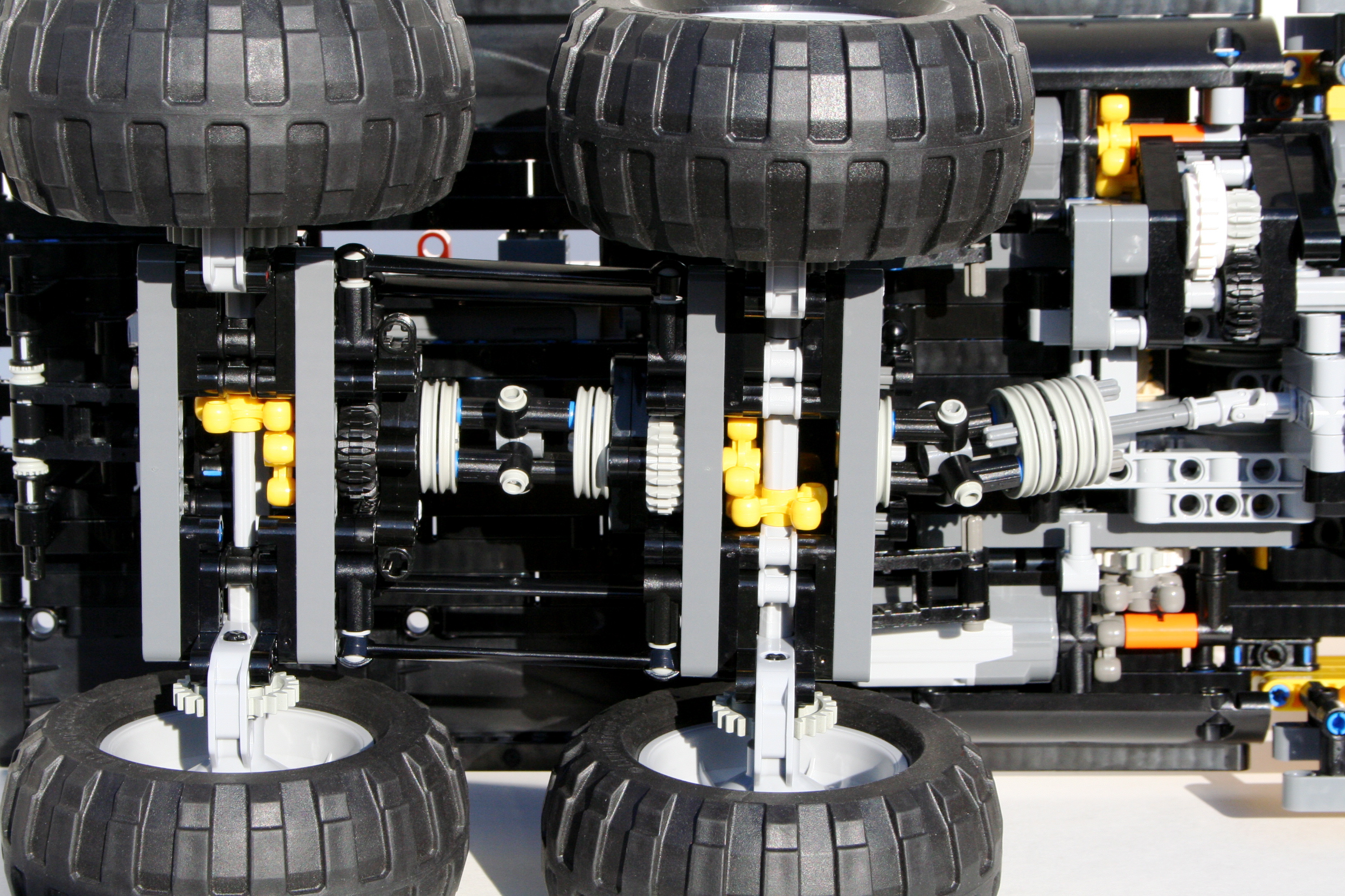
As I always do, I stared with the dimensions of the vehicle.  The schematics for the CAT 573C were easily available, so I stared with the chassis.  I knew space would be an issues, so the driveline had to be simple and compact.  The Power Functions XL motor would be geared down 3:1 and mounted just behind the rear axle.  A drive shaft would move through the steering pivot to the front axle.  The rear axle would have simple pendular suspension.  The steering would be completed by two linear actuators placed on either side of the pivot with a PF M motor on top.  Simple enough.

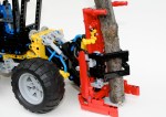
From here, things got complicated quickly.  The MOC would have four remaining functions.  The feller saw, the grapple arms, the feller tilt, and the feller lift.  Since trees are rather heavy, fellers are designed with as many of the system mechanics behind the rear axle.  As such, all of the functions I would add would need to be in the rear, as the front would not have any space.  I quickly learned this would not work.

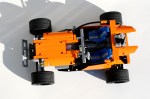
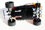
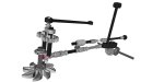
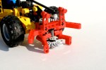
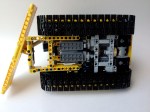
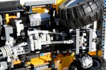
Eventually, I found what would fit.  The IR Receivers would make up the rear bumper, and the battery box would be directly over them, off to the left.  Two PF Ms would be on the right and would drive two mini Linear Actuators.  These would move two pneumatic valves. These pneumatics would move the lift function and the grapple arms function.  An air tank would supply the pressure from a pneumatic pump placed on the driveline.  Another PF M would be placed over the front axle to give the feller head the tilt functions (it should be noted, 7 designs, and five weeks were spent on this feature alone).  The final PF M was in the feller head, and would drive the feller saw.

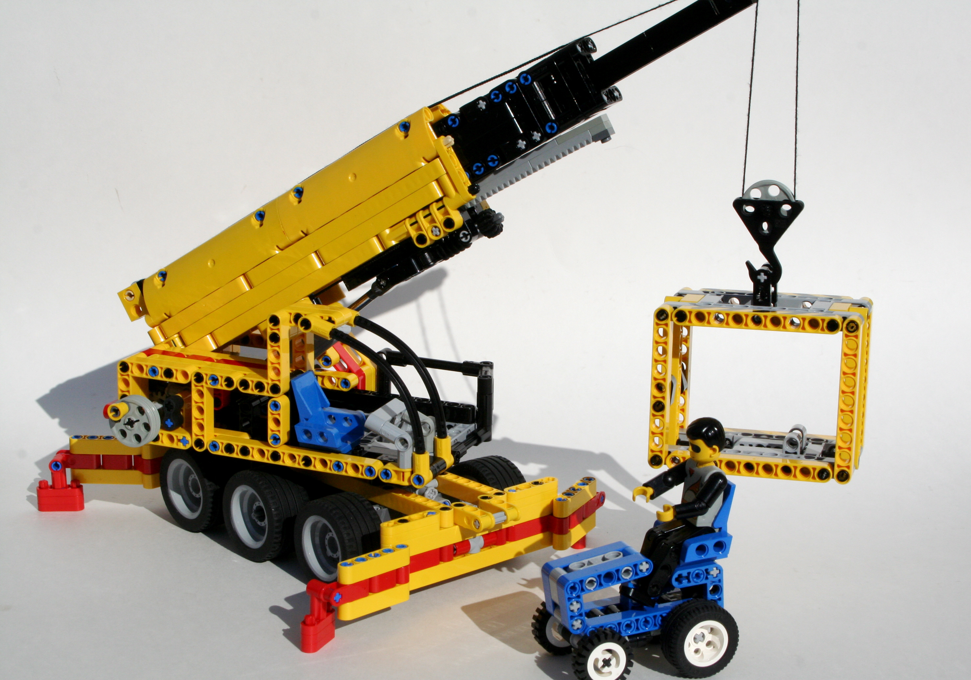
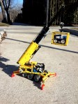
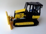
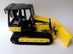
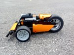
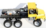
After packing, repacking, and packing again, all the features we set.  Then all the cabling and hosing were placed.  No easy task, as I was running out of space, and 25 or so hoses, and 10 cables take up a lot of room.  I added some comfort features to the cable, including a (half) chair and a roll cage.  And so Mr. Technic could get in, a little step.  Then a lot of paneling for the rear, including some access doors on the rear, and the model was done.  Here it is in action.

As you can see in the video, the MOC worked well, but some of the functions did not work as clean as I would have liked.  The drive and steering were fine, with an easy drivability.  There was a lot of mass in the back, so sometimes the torque from the drive motor would cause the back to tip.  The saw worked well enough, and for the most part so did the tilt, but the pneumatic lift struggled.  It was a little overloaded because the saw unit was too heavy.  The grapple arm worked well, but for both pneumatic rams were hard to control.  As always with LEGO pneumatics, they too often are off or on.

Until the next MOC, happy building.

Cargomaster Crane


We all have our favorite LEGO sets.  Then we also have sets that we think were pretty cool.  Set 6352 from 1991, the Cargomaster Crane was one of these sets for me.  It was a set simple set, it was perfect for a growing child.  Small, playable, yellow, and it could lift things.

Recently, I decided I wanted to make a little Technic crane.  I researched a number of designs, none of which really struck me as something I wanted to pursue.  I kept coming back to 6352. Why not make a crane like that?  Perfect.  I wanted it to be a nice homage to this classic set.  I was going to make is just like 6352.  Double the size, same shape, complete with container and tractor, and of course a driver.  The full gallery may be found here, and instructions can be found here.

6352 Technic

I stared with a simple frame built for the outriggers at both ends.  I knew I was not going to be able to add a more complex outrigger system at this scale that would reflect the original crane, so I made manual outrigigers just like the original.  I added two steering axles so the crane could drive to and from the site, then I placed a turntable right on top of the chassis.

As I started the superstructure, it become very clear very early, that having an offset crane boom like the original model, was not going to be a good idea.  My model was going to look off, and the balance of the offset boom was going to make stability, both for the superstructure, and the crane as a whole, a problem.  I knew the size of the boom, and decided to place it in the center of the crane.  I then placed the cabin, and set it up for the little technic figure.

The boom was relatively simple; two stage, and 23 studs long.  The outside was simple and straightforward, meant to be sturdy and strong.  The pivot was at the rear on top of the winch, and the elevation ram was connected forward under the front of the boom.  There was a simple worm gear under the front that would drive a set of gear racks, to drive the inner boom.  The inner boom would hold the final boom which was only a series of plates.  Each stage was connect by a two cables to make sure all the booms moved together in unison.  It worked well, even under load, as you can see in the video.

The model worked well, and had perfect balance.  The simple boom extension worked well, as did the winch.  The outriggers gave appropriate stability through all positions.  And it looked very similar to the original model, even with the little tractor.

Talon Track


Every once and a while I see something so creative I have to build something like it.  I happened with my HH-65.  It happened with my Zil 132.  And to some extent it happened with my Spitfire.  But when I saw the Urban Buggy from Chrismo, I though I have to make something like it.  It was such a fresh and creative design.  It had such great lines, a perfect stance, and a unique driveline setup.  But while imitation and outright plagiarism are the most sincere forms of flattery, I thought something of my own design would be a better contribution to the LEGO community.  I present my Talon Track Car.

You may find the full gallery here, and the instructions here.

I designed this car to be fast and stable, just like a track car.  I started with a drivetrain that would be reliable and effective.  A PF XL for drive, and a PF M for the steering.  I placed the PF M in the front mounted directly on the suspension unit, with a return to center spring in the middle of the mount.  The system is set up differently than in my Rumble Bee, but uses the same return part.  Each suspension arm would have a single shock absorber.  Directly behind the steering motor was the XL for the drive.  It was geared up with a 20z/12z ratio, with the driveshaft connecting directly to the 20z gear that turned the differential.  The rear suspension used an independent setup that was developed a long time ago for my Red Car Bigger (great name, huh).  If it’s not broke, don’t fix it.  The suspension was planted.  I placed the rechargeable battery box and the IR receiver behind the rear axle.

The car was quick, and didn’t have any problems, but faster would have been cool.  The return to center system worked well, especially for the quickness of the car, and the quickness of the steering.  It was easy to control.  The car was robust, and crashed well.  So go ahead and build your own.  Enjoy.

Mini Skidder


My Mini Feller started after I made this MOC.  I wanted to do a small little project, and I wanted to do something fun and simple, and I thought the Mini Feller would be a great partner to the Mini Skidder.  The skidder is a simple design, that uses simple construction techniques, unlike the Feller.  Also, you can build your own.  Feel free to check out the instructions here.

I started with the rear grabber.  I added a simple worm gear to 8z connection that moved one of the arms, and connected it to the other arm with a 16z to 16z connection.  The axle that connected to the worm gear would exit out of the top of the grabber and allow for movement with your hand.  I attached it to an arm that would attach to the MOC.  The arm would be connected by two arms on each side of different lengths, so the grabber would move in an arc, and connected to the chassis.  On the chassis I connected the rear arm to a 24z gear, and placed a worm gear above it.

I connected the rear part of the skidder to the front part with the new small turntable.  This allowed for simple gear connection with a 20z gear to the Hand-Of-God steering.  This worked well, and kept the model simple.  Just in front of the steering mechanism, I added another 24z gear for the plow.  Taking a cue from set 8069, I set the worm gear vertically, and connected it to the exhaust stack; simple and pretty.  I then filled in the space.  A simple body was added, as was the plow, and wheels, though not in the cleanest of ways.

It was fun little design with simple solutions for the functions.  It’s not as complicated or compromised as my Feller, but still a playable MOC.  Also, its easier to build should you feel the need.

The full gallery may be found here.

Thanks for reading.

Mini Feller


Building with Lego is a continuous formation of compromise.  While my ideal of what my Mini Feller would include was significant, what I could actually accomplish was a compromise of space, function, realism, and frankly the amount of frustration I was willing to tolerate.  So while the final result is a watered down version of what I would have liked, it was the result of me compromising amidst the situation.

Instructions can be found here.

I wanted to make a small model go with my Mini Skidder.  The MOC had to be the same scale, have a decent level of fuctions, and work with my Skidder.  A feller seemed like a good option.  As I looked at what function this MOC would have, I ambitiously stated it must have a working blade, working steering, working grapper, and a working tilt function.  All these functions would be controllable on the back or on top of the cab.

The steering was simple enough.  I added a small turntable at the bottom of the chassis to give the frame some support.  The HOG steering axle would come out at the top of the cab, and join the front and the rear with a small link arm.  Simple enough.  Likewise, I added a differential in the rear part of the chassis, geared up the rotation, sent it though a couple of universal joints to the front of the Feller, connected it through a pair of 12z bevel gears, and attached a saw blade.  Again, simple enough I had steering and a working blade.

It got complicated as I tried to add the arm features.  The lifting of the arm would be done with a 8z gear with a worm gear.  Because there was a driveshaft to the front blade, the 8z gear needed to be placed on the axis of the arm, but out of the way of the driveshaft.  The required a 1 stud offset that also needed to be directed back through the steering axis to the rear of the Feller.  I used a CV joint to allow the axle to slip as the feller would steer.

The tilt feature would require a parallel control that would allow the elevation happen while keeping the feller blade parallel to the ground.  This would require another 8z worm gear connection at the lower rear pivot point of the arms.  I was running out of space.  Of the 7 studs to work with, one was used for the universal joint, one was used for the lifting gear, one for the mounting liftarm, and one for the lifting arm.  I could not add another worm gear system, while being able to actually lift the feller blade.  Additionally, adding a link for the gathering arms would also have to work through this pivot point if I wanted to isolate the movement from the lifting and tilting feature.  I had to give.  A compromise was necessary.  I felt the stability of the feller blade had to be paramount, so I added another support arm.  I also felt gathering arms must remain as they are essential to a feller.  Sorry, but the tilt feature got the ax.  It was the correct decision, but it still tasted a little sour.

It was a great little MOC, and I had a good time creating it.  I hope you enjoy building your own.  The full gallery can be viewed here and the instructions can be viewed here.

Thanks for reading.

Flat 6


Every once and a while I get picked up by another LEGO blog. I am honored when it happens as it show others value my work. However, it seems to happen when I lease expect it, and in creations I find fun, rather than significant.  Thank you none the less.

Thanks to the Lego Car Blog for posting my Dune Buggy and my Zil 132, and The Brothers Brick for Posting my Rumble Bee.  Spreading thirdwigg is deeply appreciated.

thelegocarblogger's avatarThe Lego Car Blog

This monster dune buggy was unearthed by the Elves on MOCpages. K Wigboldy has included steering, all round independent suspension and, best of all, a huge six cylinder engine hanging out the back.

View original post

Mack Marble 5T


I confess.  I took the bait, and started on the 2012 You Design It, We Build It before the final rules had been confirmed.  I should know better.  After all my schooling, you would think I have a good idea about how to follow directions.  The first direction is, wait for directions.  But, with all LEGO building, I enjoy what I am creating, and so even after the rules and directions have been given, I still want to contribute to the LEGO community.  So, my next MOC is another Trial Truck, built with the intention of being easy to play with, easy to build, and tough enough to handle child play.  All with instructions, so you can build one.

See Instruction Page

I built this model based on what I thought could be improved on set 9398.  While this new set was a great step forward for the LEGO company, I felt there where a couple of changes that should be made to make the model a better off-roader.  Because I was working with the assumption that this would be something LEGO would produce, I gave myself a couple of constraints.  First, the model had to be less than, or equal to, the cost of 9398.  Second, the model had to have improved off-roading skills.  Third, the model had to have easy playablity, so the drivetrain had to be reliable, the battery should be easy removable, and it should be easy to drive.

I started the frame before the axles.  I placed the battery box directly over the driveshaft.  An XL motor was place behind the BB and three 16z gears above the driveshaft.  One 16z gear went up to the fake motor shaft.  The driveshaft would connect front and rear to the two axles through the new ball joints from 8110.

I then built the two axles, starting with the rear.  To keep the speed of the Mack similar to the 9398, I would gear down the XL motor to about 1:4.  The driveshaft came out of the ball joints and connected to the differential.  I chose two 12z/20z gear sets as the final reduction.  This would keep the driveline a little stronger, and help keep various axles from working their way out of the gears, much like the design of the 9398.  The final gearing was 1:3.89.  It’s not a stump puller, but it could still move up most hills.

The front axle was a little more tricky.  Basically, it had a similar setup, with a PF M motor placed on in it to work the steering.  This was by design.  To keep the driveline reliable, and limit the failure of steering, I kept the steering part of the axle, rather then having components placed in the chassis, and then connected via a shaft to the front axle.  The steering is a little quick for my liking, but it works flawlessly.  To understand more about the axles, check out the instructions.

Through a little trial and error, I connected the suspension, and tweaked it so it would function in a way that was robust, and allow for great movement.  I am still not pleased with how it turned out aesthetically  but it functioned without problems, it supported the model well, and allowed for sufficient articulation, so I left it.

I then added a simple body, a basic rear bed, and added some engine components such as exhaust,  intake, and a simple turbocharger behind the fake motor.  When I was done, I noticed the cab looked a little like an old Unimog.  This seems to be a theme with me, as I love the look of the Unimog.  On the other hand, I do not like the look of too many cabover truck designs, as such, many of my trucks have the slight setback cabover design that is very similar to the Unimog.  My T55 is like this, and this is why I have built so many Unimogs.

The model worked well.  the suspension and stability was perfect.  The truck was stable, and did not roll over, all while being able to handle various terrains.  The gearing was sufficient and would be great for a playing child.  It was easy to change out the 12z/20z gears in the portal axles to a 8z/24z setup which made the truck a little more strong.

It would be a great model for many LEGO fans due to cost, reliability  stability, and playability.  So I have posted instructions for people to enjoy the model as well.  I think it would have been a great LEGO set, then the rules were released.

Next time I’ll wait for the rules.  Thanks for reading.

Full gallery is here.

CAT D5K


Construction equipment was pretty much designed for LEGO Technic.  I learned this while designing my MB Axor Refuse Truck.  Yellow bricks are pretty popular and accessible, the equipment usually has many functions which can be replicated, and working models with power functions can be made to reenact various construction projects for great playablility.  After finally getting some large track links, I figured it was time for me to do a bulldozer.

I wanted to model the CAT D5K for a couple of reasons.  First, it used a two wheel track for each side rather than a three wheel track for each side.  Second, I wanted to do something by CAT.  Third, I decided on the D5K because for dozers of this size I think it looked the best due to its stance and overall balance.  Plus, when I started looking at the scale of the dozer I was to model, I learned the D5K would work best with the parts needed such as the tracks and blade, and work with the internal space allowed.

The base D5K really only has three functions: drive, blade lift, and blade angle.  I had no intention to add a ripper, because, frankly, I ran out of space.  Space became an issue very early.  I had 9 studs to work with between the tracks, and I needed to add four motors, a dummy motor, a battery box, and two receivers, all while retaining the appropriate look.  All the gearing had to be compact, and the linear actuators needed to be placed efficiently.  The real D5K has a manual adjustment for the blade pitch, but all of my designs left something more to be desired, so I took it out.

Both tracks would have their own motor, and I wanted to link them to a dummy engine, which required a differential.  I connected the motors directly to a worm gear which drove a 8z gear.  This gear was on the axle for the rear drive wheel, and connected on the other end to a differential which connected both drive wheels.  This differential functioned as a power take off for the dummy motor in the front of the bulldozer.

Two more motors were placed under the dummy motor.  One connected though a 12z/20z gear reduction for the blade angle.  It proved difficult to supply power for the blade angle function through the blade tilt pivot without taking up too much space.  The second motor was used to adjust the blade height.  After a simple reduction, two mini linear actuators were used to move the blade up and down.  It worked well, and was plenty strong.

I added the battery box under the driver’s seat, and placed the two IR receivers in the top of the cab.  It was not optimal aesthetically, but it seemed to work well for control.  And again, I just ran out of space.  I worked on the body, gave the model a working hood, and built a cabin.

The model worked well, but building with tracks is always a little bit frustrating.  Like it or not, LEGO plastic will never be fully smooth, and this is compounded with the track system.  Also, I found that the dummy motor would lose its connection to the drive wheels, as the axles connecting to the differential would slip out every once and a while.  This seems to be a commom problem with Technic builders, so we will see if the new axles will help.  I liked the size of this model, and it had a good amount of functions.  Now I need to use the tracks for something else.

Maybe another tank.

The full gallery may be found here.

Rumble Bee


It has been six years since I bought my F1 Wheels and Tires.  I bought four, and I paid a lot for them.  To date, I have used them once in my Red Sedan; and only two of the four that I own.  For some reason, I decided I needed to use them again and I wanted to do a small little project.  I was recently reminded about a childhood video game P.O.D. racing, and thought the car I was designing would fit right into the game.

The car is a simple design; a drive motor, a steering motor, a battery box, and a receiver.  I knew I was going to design a three wheel car.  I wanted to have the rear wheel driven by a PF XL, and a single PF M with a simple return to center system for the steering.  After a couple of designs, I decided to place the PF XL motor in the hub of the single rear wheel.  I tried a couple of designs to gear the motor up for a little more speed, all with various locations in the car.  Nothing worked as well as I wanted.  The speed was sufficent, and placing the motor in the hub allowed for a super short wheelbase.

Because the PF XL was place in the rear, I had a lot of space for the rest of the Power Functions equipment.  I placed the battery box directly in front of the rear wheel right at the bottom of the car.  The front steering axle was place next in front of the battery box.  The car had a short wheelbase of only 18 studs.  On top of the battery box, I placed the PF IR reciever and the PF M motor which was for the steering.  The steering motor passed an axle straight through a Spring Loaded Connector to move a 3L liftarm which connected to the steering rack with a 6L steering link.

I added a simple body using the orange panels from 8110.  Keeping with to story of P.O.D. I wanted to keep an agressive stance and look to the car.

The car ran well, and was plenty quick.  The steering was sharp and the car was well planted on the road.  I had a good time with the design.  Now I need to come up with another use for my F1 wheels.

The full gallery may be found here, and instructions here.

Freightliner M2


For some reason, I often find myself building two trial trucks at the same time.  While I was building my ZIL 132, I also wanted to try something with floating axles.  The model would use 6 wheels, a 3 speed transmission, and fully suspended live axles.  I also wanted to model the Freightliner M2 Business Class truck as closely as I could.

The model started as my trucks usually do; with the axles.  The second and third axles would be identical, and would be connected with a simple pulley wheel universal joint between the two.  To keep the speed through the universal joints high, and the torque low, I used as 12z/20z gearing after the universal joints, then the knob wheels to rotate the axis, then the normal 8z/24z gearing on the portal axles to finalize the drive.  This also allowed me to keep fewer knob wheels as the second axle had the drive shaft from the transmission pass uninterrupted to the rear wheels.  The final drive ratio for the two rear axles were 1:5.

The front axle was a little more work.  I wanted to have the steering motor mounted on the axle so I would not need to have a steering shaft connect to the front axle.  This proved too difficult, as it would raise the PF XL motor that I was going to use for the drive to high on the truck.  I decided it would be better to mount the steering motor on the frame and connect to the front axle via a CV joint.  Once I made this decision, the front axle became easier.  I used a 1:3 gearing on the portal axles, a knob wheel, and then a drive shaft back to the transmission.  The steering axle would exit just above the drive shaft on the axle to move to the right for the steering motor.

The frame was pretty simple.  Once I had the transmission placed, and the axles spaced, it was simple to place the suspension components, and the shock absorbers.  Each axle had two steering links mounted vertically which connected to a 3×5 liftarm which would activate a shock absorber; very much like Lyyar’s design.  Each axle had a steering arm to keep the axle from swaying laterally.  Finally, all three axles had a number of 9L links to keep the various movements maintained.

The transmission was going to be placed behind the PF XL motor which was under the hood.  The changeover mechanissm would be placed in the center of the truck with the changeover motors mounted longitudinally, on both sides of the truck.  The PF XL motor was place directly above the first axle, and was mounted on a moving frame that was moved by the changeover.  This allowed a moving frame to work its way through the three gears.  The ratios were 1.25:1, 1:1.25, and 1:2.  This allowed for final ratios of 1:4, 1:6.25, and 1:10, which was more than capable for most terrain.  The drive and steering Battery Box was mounted over the second and third axles, and the gearbox 8878 battery box was just behind the changeover in a little box on the bed of the truck.

Finally, like always, a simple body was mounted.  I had a little trouble getting the look I wanted on the front of the hood, as the suspension components kept getting in the way.  I added a bed, covered the changeover and motors, and a couple more details and everything was finished.

The model was not my best driving truck, as six axles do not want to always work together.  The suspensions was supple, and I was getting no drive or steering input on the suspension.  The truck worked well over various terrain, but struggled on some on step obstacles.  The transmission mounting worked well at changing gears, but gears did not have a strong support, and I found they liked to skip at times.  I liked how the suspension worked, but I do not think it brought enough of a valued to use this system again.  It had moderate improvement on dealing with terrain, but it placed a lot of stress on a number of parts, such as the frame, the axles, the driveshafts, and the universal joints.  The next truck will use a pendular set up again.

The full gallery may be found here.