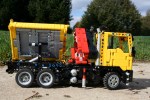
K-Tec 1233 Scraper


I find myself on diecastmodels.co frequently as it inspires many of my future builds. Most of the time the site gives me reference pictures, and sometimes it shows me something I have never seen before. This is the result of one of those late night browsing sessions.

See the full gallery at Brickshelf and on Flickr. Instructions may be found here.

K-TEC 1233

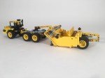
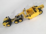
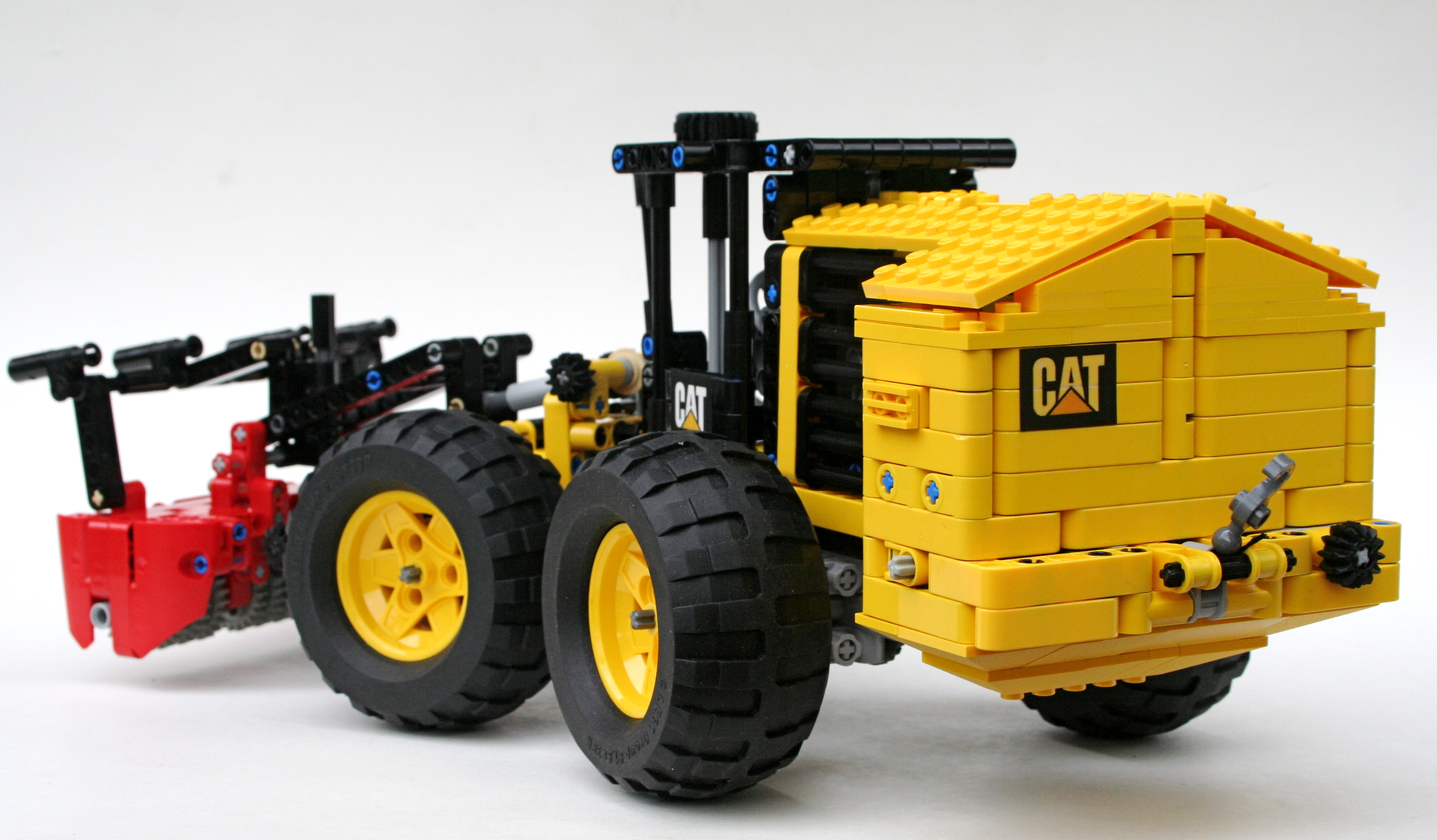
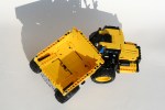
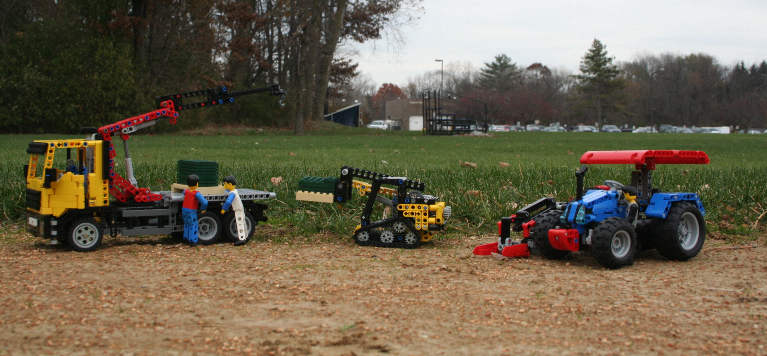
I wanted to make a scraper, and once I was browsing this site, I came across the K-Tec. It was a different set-up that I thought looked fun. I was hooked. Early I decided the MOC would be perfect for the newer 49.5×20 tire, so the tire set my scale.

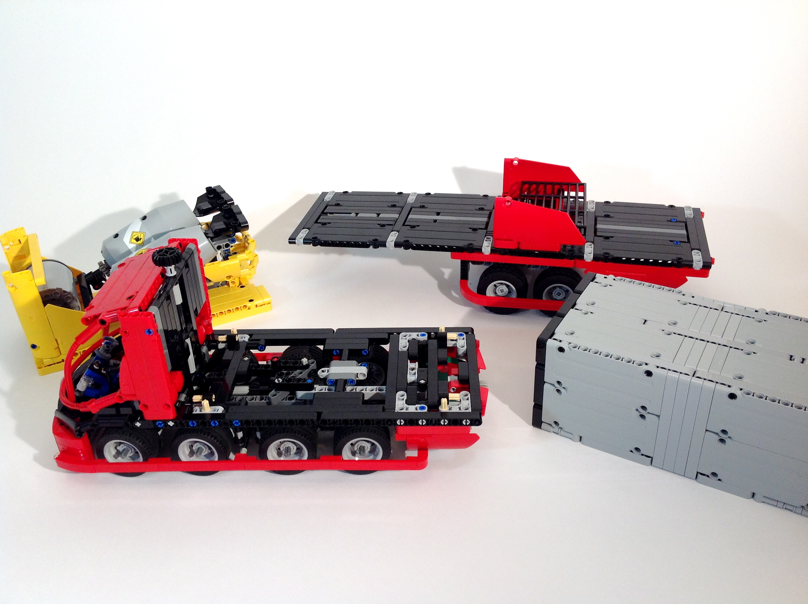
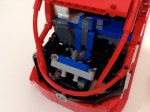
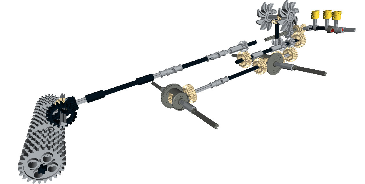
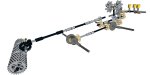
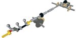
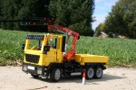
I started with the suspension for the tractor first. I did not have too much room to work with on the rear, so I set two differentials together, and connected them via two 20T gears. The rear one connects above to a 12T gear, which transmits rotation to the fake motor in the front. The two axle assembly pivots at this gear connection and connects to the rear wheels, so no u-joint is needed. The middle axle connects to the rear assembly through the differential connecting axle. This simple set-up allows for all four wheels to move freely, and independently.

K-TEC 1233 ADT Suspension

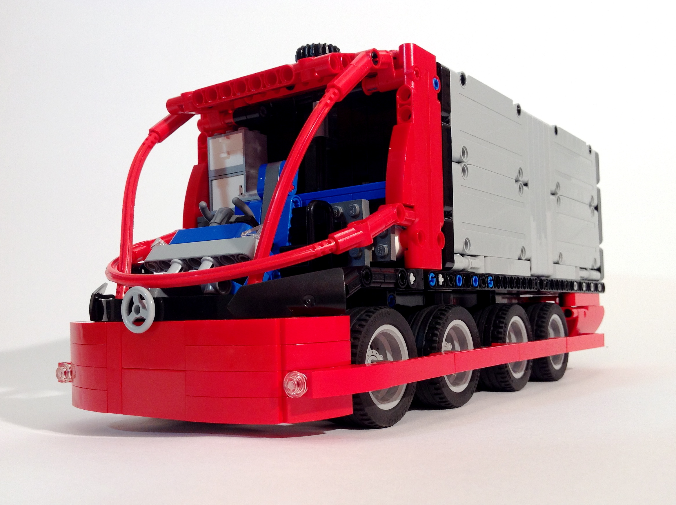
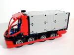
I then added the front cab. It is not too complex with a differential fixed for the front axle, and a two-cylinder fake motor above it. A HOG gear is above the cabin which pulls a liftarm for the steering. A turntable is used to provide articulation between the cab and the rear chassis. Then a simple body was made, and off to the scraper.

K-TEC 1233 Tractor

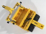
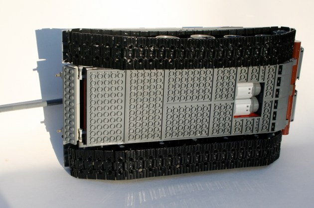
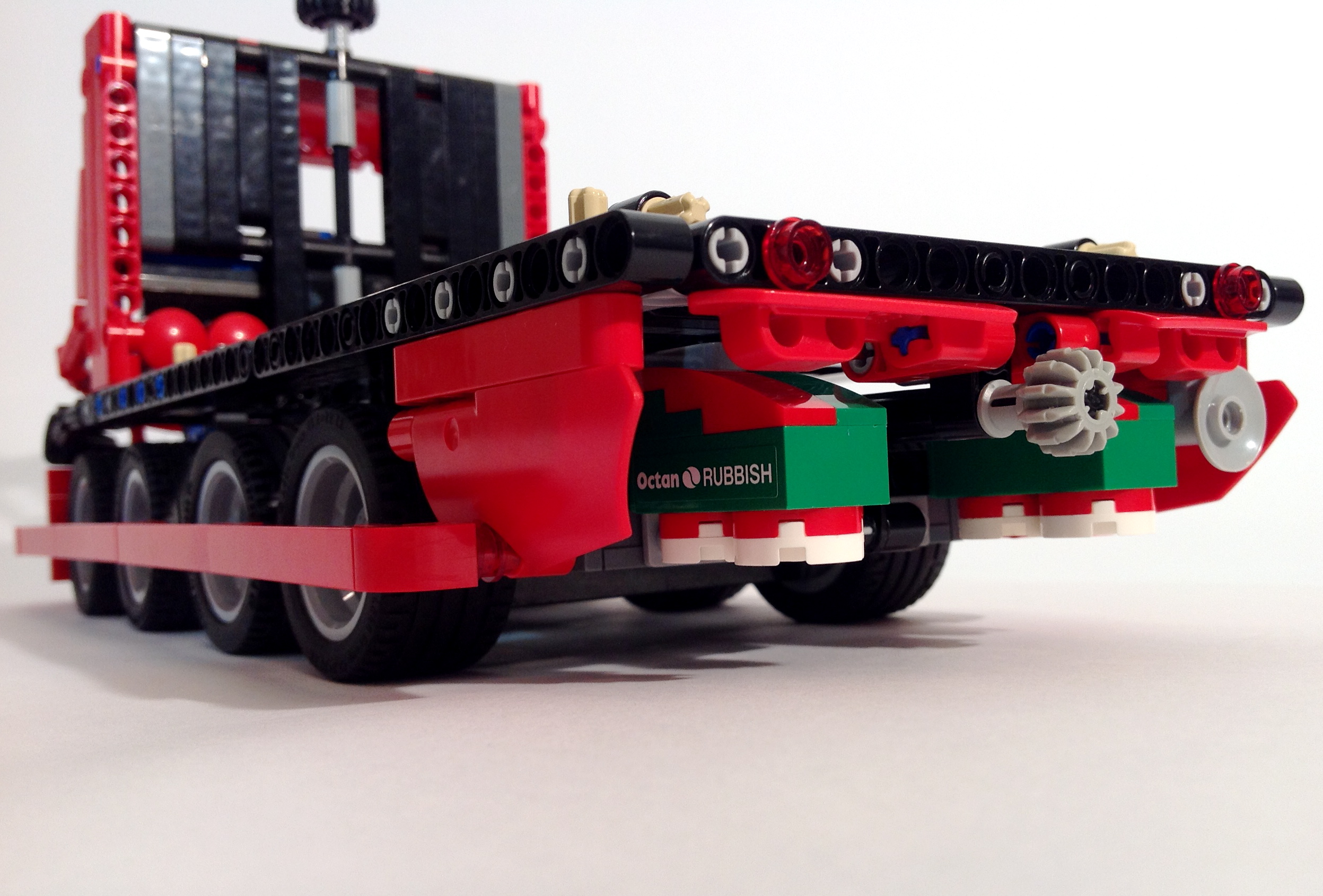
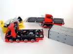
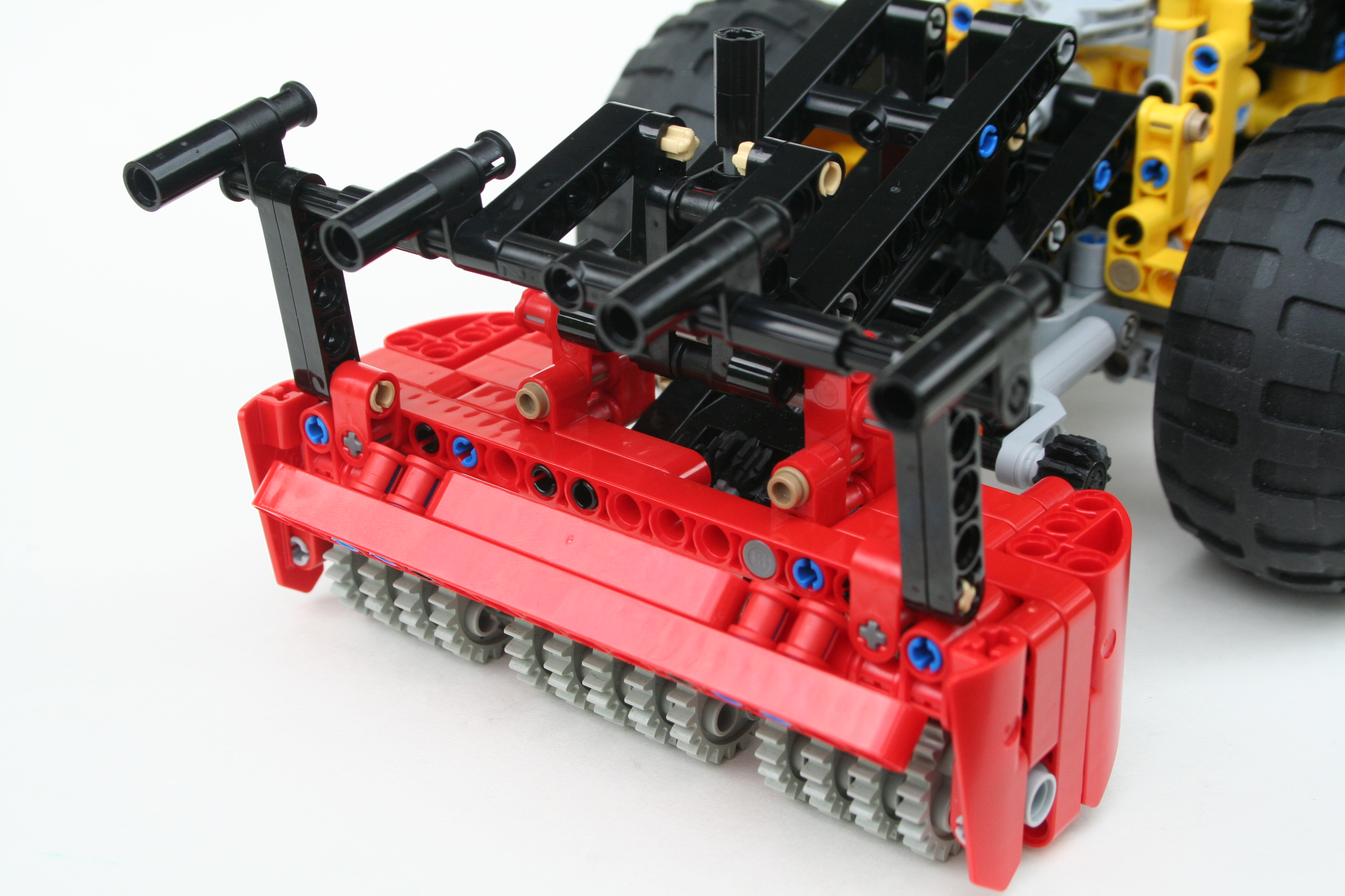
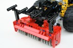
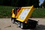
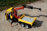
I then worked on the scraper part; kind-of. I knew when I started this project I would need a bunch of 1×6 arch bricks in yellow for the front gate. There are not many of them, so I started ordering them over the course of three months. As each would  arrive, I worked on the scraper. I first set the dimensions and worked on the lifting mechanism. It was a little tricky to find the correct geometry while not taking too much room, and keeping the upper pivot point small while using to mLAs for the movement. I found a good solution, but a little more stiffness in the assembly would have been great. I added an extraction plate at the rear driven with a worm gear assembly resting between the rear wheels. Another stud of travel would be great, but it was not worth adding another four stud gear rack to make that happen. Finally, all the parts arrived for the front gate, so I installed it. Because the walls of the scraper are only one stud thin, I did not want to mess with the thickness of the sides to much by adding a mechanism for the gate movement. Each assembly I tried with a mLA or a worm gear set-up looked clunky or bulky. I ended up with a friction pin with a gear to move it. It is not very fancy, but it works well. At this scale, it is all that needed.

K-TEC 1233 Gate

All in all, the MOC turned out OK. It would have been better to have a stiffer hitch arm, and I would have liked a different solution for the entry gate. I was pleased with the size, and I enjoyed packing a number of features into the small (but long) MOC. Finally, for some reason the MOC does not please my eyes as much as those first pictures I saw on diecastmodels.co. Maybe it just needs to be a little bigger.

Until the next one, Happy Building.

T-55A


The T-72 that a made a couple of years ago is still the most popular MOC I have made; at least in terms of internet analytics. This year, I committed to making another tank, so I figured keeping in line with old Soviet armor would be rather apropos.

The main gallery may be found on Brickshelf or at Flickr. Instructions may be found here.

T-55

The T-54/T-55 line of tanks have been produced in greater numbers than any other tank. The MOC represented here is a T-55A, representing types that were assembled starting in 1970. This series included an updated NBC and antiradiation system, an upgraded engine, and also added back in the 12.7mm anti-aircraft DShK on the loader’s hatch that was part of the original T-54 spec.

As with most of my MOCs, I starting scaling the tank before any building took place. I knew I wanted to use the newer, larger track links, and I knew I wanted to use the old mid-sized wheels. This set my scale, so I got to work. Starting with the chassis and the hull I worked first on the driveline and suspension. I used simple 2×4 liftarms to connect the road wheels to a suspension axle which activated a shock absorber inside the hull. Each road wheel has its own shock absorber. Fitting them all in took some creativity, but they are all mounted inside on the left and right sides of the hull. In the end, each wheel has about 3 studs of vertical travel.

T-55 Chassis

In between each suspension bank are the remaining mechanics.  After the suspension was set, I worked on the turret functions. Right from the beginning, I knew the tank would have a rotating turret and an elevating gun. It was clear having the elevation mechanics for the gun in the turret would be tight, so I decided instead to have the functions placed in the hull rather than in the turret. Using a vertically mounted mLA, connected directly to the breach of the gun, I was able to develop a method that would elevate the gun throughout the full turret rotation. The turret rotation was driven by a 8z gear connected to the turntable, and reduced by a worm gear. Both motors for the elevation and rotation are placed directly in front of the turret.

T-55 MechBehind the turret are two PF L motors mounted transversely side by side. They drive a 1:1 gearbox which connect directly to each rear drive sprocket. The IR receivers are placed above the gearbox. For those keeping score at home, the internals are (f to r) the battery box, the turret motors, the turret mechanics, the drive motors, and finally the IR receivers.

Working on the exterior of the MOC is what took the most time. The hull came together pretty quickly, with the exception of the details over each track. Most of the finishing time came with the turret exterior. Most Soviet tanks have the distinctive mushroom turret, which considering LEGO’s cube orientation presented some challenges. The turret of the T-55 also has a slight triangle orientation when viewed from the top. Like the T-72, I designed the turret with four side orientations (left, right, front, and rear), and one top orientation. Starting from the rear, I added a basic curved structure. The sides each had a couple levels of slopes, each tapering in toward the gun. The front was a little more complex. There are two “slope blocks” made of 4 curved slope bricks, and a supporting structure. One slope block is mounted on each side of the gun. The support structure is a mess of bricks with a stud on one side, headlight bricks, and plates. The top of the turret is plates on the front, and two sloped plate sections under each hatch. The two hatches are mounted to the turret support under the sloped plate sections. The AA machine gun is placed on the top, and various external mountings are placed in various ways around the turret.

T-55 Turret Detail

After making a lot of non-powered MOCs, it was nice to get back into Power Functions. I was pleased that everything worked flawlessly. The drive had adequate traction and power. The suspension worked well, and provided good floatation and travel. The turret rotation was smooth and allowed for precise directions changes. The gun elevation worked great, though I had to limit turret rotations to under four before the clutch on the mLA would snap. After a number of smaller builds, and frustratingly long builds, I was nice to finish something that worked well, provided constant entertainment throughout the build, and turned out quite nice.

Happy building.

2045 Mercedes-Benz Athane


I enjoy participating in LEGO contests, but I cannot join all of them. Sometimes the timing, my build interest, and the available parts all line up in a way that I can submit an entry. I was able to submit something for the LEGO Technic Mercedes-Benz Future Truck Competition hosted at Rebrick.com because everything fell into place. I hope you enjoy the submission.

The full gallery may be seen here (flickr) or here (brickshelf).

Mercedes Benz Athane

While I would love to see us progress to flying and fully autonomous vehicles, a complete technological and transportational paradigm shift needs more than 30 years; see where we were in 1985. I envision transportation in 2045 will be affected by a couple of features:

  • Cities will be more dense
  • Active transportation will occupy a greater share of road users
  • Electric charging options will be more available and more diverse
  • Vehicles will still have drivers, but the drivers will be heavily assisted with technology
  • Fossil fuels will still be used, but significantly reduced and not limited solely to petroleum
  • Cargo will not change, but storage will
Various loads to apply to the Athane via the SmartStack System.

Various loads to apply to the Athane via the SmartStack System.


With this is mind the 2045 Mercedes-Benz Athane has been designed to best fit within this context. While taking this context into account, the Athane prioritizes three values as most important: Safety, Sustainability, and Versatility.

Placement of the large methane tanks. ThermoCommLink on right rear bumper.

Placement of the large methane tanks. ThermoCommLink on right rear bumper.

Here is the Press Release-

May 22, 2045, for immediate release

The 2045 Mercedes Benz Athane prioritizes safety, sustainability, and versatility. The 2045 Athane is the most advanced and cost effective truck in our 150 years of truck building experience.

As cities become denser and multiple transportation modes are becoming more prevalent, road safety for all road users must be paramount. The Athane’s ThemoCommLink (TCL), located on the right front and right rear bumpers, allow motorized vehicles to communicate to one another. The TCL also detects the heat signature of pedestrians and cyclists. Identification and communication with other users, keeps all road users safer. The driver is seated in the center and forward in the cab to increase vision. Retention of a human driver allows for relational interaction at the job site, and helps the technology make good decisions about varying road situations. The TCL Technology assists the driver so fewer errors are made. The front bumper shaping and full length wheel guards lowers the severity of crashes with non-motorized users should they occur. The Athane uses eight steerable wheels to improve weight distribution and increase city maneuverability. While many manufactures are switching to floatation and hover type drivetrains, this setup allows for unmatched braking control, and removes disruptive air currents to those walking and cycling close to the moving truck.

The Athane’s Methane-Hybrid driveline continues Mercedes Benz’s prioritization of decreasing fossil fuel use. The Athane uses electric propulsion using energy stored in the batteries under the cab and bed. Battery charging is done by braking and by a small methane powered combustion engine behind the cab. Additionally, the Athane can be ordered with an induction charger under the cab to work with newly developed induction charging roadways being installed in many municipalities. Methane gas is clean burning, and a significant byproduct of the waste and recycling process currently in place with Octan Rubbish. A partnership with Octan Energy and Mercedes Benz has developed a standard way to reap, store, transport, and fuel the Athane’s regeneration engine using methane gas. Removable methane tanks are house behind the rear wheels, and in smaller tanks in the cab.

Today’s logistics companies are searching for ways to improve versatility and lower cost. The Athane’s SmartStack systems allows for interchangeable bodies, cargos, and applications all with one common truck. The SmartStack system makes it easy to change the load in just minutes. The connection fits the international container standard. Many body work designers are applying this standard as well. In one afternoon, you can ship a container, deliver a load of concrete, and pull a fifth-wheel with the standard hitch.

Welcome to the future. The 2045 Mercedes Benz Athane keeps all road users safer, decreases our harm on the planet, and supports all work tasks needed.

Features:

  • 8 wheel steering
  • Sleeping bed
  • Aerodynamic cabin
  • In-cab Storage System
  • ThemoCommLink, front and rear
  • SmartStack System
  • Fifth-Wheel Hitch
  • Wheel Guards
  • Large/Low Bumper
  • Methane Tanks
  • Hybrid Motor
  • Induction Charger
  • Batteries
  • Passenger Jump Seat
  • Front and Rear Lighting
  • Video Mirrors on Each Side of the Steering Wheel
  • Visibility Focused Driver Placement

CAT 586C


My favorite constructions vehicles are feller bunchers. The wheeled ones. So I am naturally inclined to make them. I built a small one; I built a large one. I wanted to build a medium one, but I figured I should get out of the box. At least this time.

The full gallery may be seen here, and instructions may be found here.

CAT 586C

The CAT 586C is a site prep tractor. Forgive me for simplifying the work done by the engineers, but the tractor is basically a 573C with a new implement for site preparation, rather than felling. As always, I stared with scaling the full tractor from CAT’s website, and finding a size that would work well with tires, features, and aesthetics. Then I started building.

CAT 586C Rear

I started with the chassis, to get a sense of the size and the layout. I had a good idea of all the features I would want, and I knew some planning would be required. I then finished the mulcher (implement), which is basically a rotating drum with lots of teeth on it. I used a bunch of 24 tooth gears, and connected them to a rotating driveshaft. The chassis was built with four wheel drive, and was connected to the mulcher driveshaft through a series of gears to increase the speed of the drum.

CAT 586C Underside

Then on to the back of the tractor. Feller bunchers and site prep tractors all have their engines in the back; pretty normal for large tractors with large front implements. But to get the weight as far back as possible, the engine is mounted transversely. This presented a couple of challenges for me. I mounted a I-3 engine on the left in the rear with simple gearbox geared up to connect it to the drivetrain. Just in front of the motor are the two cooling fans, which are also driven by the drivetrain. These are also geared up. For those of you keeping score at home, the drivetrain gears up three separate functions, so rolling the MOC on the floor causes a nice whizzing sound.

CAT 586C Driveline

I added some additional features that mirror the real tractor. First, over the mulcher there is a guide bar that allows the tractor to push trees and shrubs down toward the mulcher. In my MOC this is accomplished by a simple worm gear mechanism. Second, I added a small winch on the rear to get the tractor out of sticky situations. Finally, a small mulching door was installed to allow for more or less entry to the mulcher, again just like the real tractor.

CAT 586C Mulcher

The tractor worked well. Functions were smooth, and required no maintenance during play. The many controls on the front were a little dense, and this caused some finger congestion. The number of rotational features connected to the drivetrain made rolling on the floor a little strained. Thought, this kept the MOC from rolling off the table into a lot of pieces. Everything worked well enough, so maybe it is time to make another feller in this scale. Not today, I still have a lot of other projects to complete first.

Happy Building.

JCB 531


Astute readers will note the heading of Thirdwigg.com has changed to read “LEGO Technic from Grand Rapids.” A slight heading change notes a rather large life change for myself, Mrs. Thirdwigg, and Jr. Thirdwigg. This has caused a slight hiccup to production and the timeline of The Queue, but we are back in business.

A working telehandler has been on my list of machines to build for a long time. I finally acquired a 32l axle, and it was the impetus I needed to start the project.

The full gallery is here.

Ready to take on any project.

Ready to take on any project.

Right from the beginning I decided the MOC would have steering, boom lift, boom tilt, and boom extension. All the functions would be manual as is my current trent (do not fear, it will be over soon), and would be housed within the boom itself. I based the scale for the MOC on the length of the boom being 32 studs so I could use the full 32l axle.

The 32l axle was placed on the top of the boom, and would allow the sliding 8z gear to transmit rotation to the fork tilt throughout the full extension of the boom. At the end of the boom I added a mLA to adjust the tilt of the fork. It took a little working, but I eventually figured out how to adjust the tilt for every position in the lift. I then worked on the boom and the extension so it would be as stiff as possible through all points of the lift.

I then worked on the chassis and the cab. The chassis was rather basic, and after a couple of rebuilds to get the steering right, it was done. I did have to do some revisions to have the boom/chassis interface more rigid. It turns out that when the boom was fully extended, the lift would sway a little too much. I then added a cab and the engine box on the right side. Here you can see the final project working.

The MOC worked well, and other than a slight sagging of the boom at full extension, I would not change a thing.

Happy Building.

Hawker Typhoon MkIb


Two years ago I built the Spitfire MkIIa. It remains one of my more popular builds, and one of which I am still quite proud. It was not my first large plane, though when I completed it, I said it would be my last.

As my father would say, “never say never.”

Typhoon

The full gallery may be seen here.

I learned a lot of great things from the Spitfire. Large scale building is exciting, and challenging in that you have to think about significant structural considerations, placement, and shaping before and while your build.

With this in mind, I wanted to develop what I have learned, but allow myself the ability to take a large scale aircraft to the next level. I wanted to improve the function of the control surfaces, design my own propellor, use four Power Function channels, and use the boatload of Dark Green parts that I had recently acquired. I considered a number of airplanes, including doing the FW-190 again, but I finally settled on the Typhoon. Time to get building.

After some planning, I had my scale. 1/13 was an appropriate size for me to replicate the plane and its functions, while still keeping the plane from getting too large. This scale would also allow for LEGO wheels for the landing gear, and a worker able propellor spinner design. As I learned from the Spitfire, placement of large components needed to be done early, and placed in the MOC to its exact final location. As the structure of the fuselage and wings would be stressed heavily, large components could not get in the way. Once I placed the engine block, the landing gear, the power functions, and the control surfaces, I was able to start putting together the robust structures that would support the final plane. One of the major challenges of this plane was the outset landing gear on the wings. Because they were located 42 studs apart, the wings needed to be strong. But due the the space taken for the control surfaces, and the massive 24 cylinder power pack, the wings still sag a little under load.

The control surfaces were activated with strings with studs on each end. I found this to be a better system than the axle controls for the Spitfire. It kept the controls more smooth, and reduced the amount of play in the controls. The elevator and ailerons were controlled with the joystick, and the rudder was controlled by two foot pedals in the cockpit. The remaining functions were controlled via Power Functions. An XL motor powered the massive 38 stud diameter propellor, as well at the 24 cylinder Napier Sabre engine. A M motor controlled the pitch of the propellor. Another M motor powered the landing gear, and still another  adjusted the flaps. All four motor were mounted in the chin of the aircraft; I had to use that huge chin for something. The two IR receivers were mounted in under the windscreen, and the rechargeable battery was mounted behind the cockpit.

Finally, I had to make sure all the markings were accurate. Again, due the limits of dark green parts, it was not an easy task. I started with wings, and made sure to add invasion stripes, and work my way out to the tips. The roundels were a little different than the Spitfire, but were a little larger. The fuselage took a little work to make sure the panels could be easily removed, but I eventually got there. The fuselage roundel should have a yellow ring around the outside, but the strip is so small, I could not figure out a good way to do it.

The plane worked almost perfectly. The ailerons were a little sticky, but other wise everything else managed to work for an 8 hour shift at Brickworld. The plane was liked enough to be nominated for Best Air Ship. While it did not win, it was validation that the the model was a success.

Happy Building.

JCB 714


My repertoire has become quite diverse over the years. I have made large cars, large planes, MODs, and many other types of builds. I enjoy those builds, and I get an immense amount of satisfaction completed them. Recently I have enjoyed making smaller, non-powered, Technic MOCs. I can generate more small build ideas, I can stay motivated better, and I enjoy the playing with final result more. So I made another small MOC, the JCB 714.

The full gallery may be found here. Instructions may be purchased for $5 USD.

Buy Now Button

JCB 714

This MOC started when I was browsing the JCB UK website. I thought the 714 would be a fun little project that would have some nice features, and would utilize some of my collection that is not currently being used. I started working on the frame. The MOC would have a four wheel drive system, suspension, steering, and a dumping back. I designed two suspension/steering designs, and while the first one was awesome, it was not as stable as I would have preferred. So I reverted back to the design utilized on the real JCB. It was not as flashy, but it worked well. A turntable is planted behind the steering pivot, with the drive axle moving through the center of both. A liftarm was placed on the left to operate the steering function. The drive axle would connect to both axles through a 12/20 gear reduction which connected them to two differentials. The I3 motor was placed in front of the forward axle.

The rear was more challenging than I expected. First, I had to plant the mLA’s in such a way that they could be connected by a single axle that would not impede the driveline. Second, the mLA’s had to operate in such a way that the bucket could do the full range of motion; nearly 90 degrees. Third, the shape of the bucket did not work well in LEGO, as there were limited flat surfaces. Thankfully the sides were flat, and some of the bottom. The bottom was connect to the dump pivot, and the sides would hold the angled panels. Finally, it had to make sure the rear wheels could still move freely. While there are still some holes in the dump, it works well enough to transport a bunch of bricks.

The cab built up fairly quickly, and allowed me some space to add the rear window grate, and a exhaust pipe. The hood can open, and there are steps to get into the cabin. Safe egress is important.

As I am finding with MOCs that do not utilize Power Functions, the MOC functioned well, every time. No maintenance is needed, gears do not skip, and the MOC works as it is designed. This is part of the reason I am building these kind of MOCs more often. The MOC worked as it was designed, just like a MOC should.

Thanks for reading and happy building.


MAN TGS Tipper Crane


I like to have a LEGO MOC on my desk at work. I find it to be a good conversation starter for visitors. It also gives my fidgety fingers something to do while I am on the phone. Plus it’s just cool. After I finally removed my 4×4 8081, I figured it would be time to add something new.

The full gallery may be found here. Instructions may be purchased for $5 USD.  Buy Now Button

MAN TGS

After a little research, I decided to make a MOC based on a MAN TGS tipper crane truck. I knew the MOC would not have any Power Functions, so I had the space to add a number of features. The truck would have 3 axles, a 4 function knuckleboom crane, three way tipper bed with drop sides, working outriggers, and of course working steering.

I started with the crane. It gave me a little trouble, but after trying countless linkages and connections, I came up with a simple design. I worked from the hook down to the truck. I started with the extending boom which was simply a 13L gear rack, and then added it to the main boom. I used a mini linear actuator (I love these) connecting to a simple linkage to the boom could rotate nearly 180 degrees. While the linkage could be a little more sturdy, it functions well and is controlled from a gear on the back of the crane. Finally, I mounted the second mini linear actuator directly on the turntable to lift the crane. This would be controlled with a gear on the back of the truck.

After the crane, I added the outriggers directly to the turntable. After toying with a lot of complex designs, I settled on something simple. Two 13L gear racks would move to out of the truck, and a pin with stop would be connected at the end and would move to stabilize the truck. I worked with the gearing for the stabilizers and the crane, and managed to get a working system. The center of the truck is pretty dense.

Next was the bed. I developed a simple linkage that would allow another mini linear actuator to tip the bed up. I connected the linkage so the bed could tip three ways. The whole system is three studs tall. At each corner of the bed, I added a simple connector so the bed could tip each way. The direction of tip could be adjusted based on which axles are removed. You can also remove a axle for each side, so contents could be dumped in three directions.

Finally, I worked on the body and the finishing of the truck. I think I got the look of the TGS pretty close, and added features like working doors, an exhaust pipe and an intake. Also, every Technic model in this scale needs to have blue seats, so I added them.

I wish the crane on the truck could support a little more, but other than that, I am pleased with the results. I really liked how the bed turned out. It’s simple and effective. And it all looks quite nice on my desk.

Until my next MOC (or MOD?), happy building.

Instructions can be purchased for $5 USD. Send and email to thirdwigg@gmail.com if you want a set.

The Sod Farm


During two summers when I was in college, I worked on a Sod Farm. It was, let’s say, a developmental experience. The days were hot, long, and often included nothing more than sitting on a tractor listening to the diesel drone as I would slowly mow the sod at 1.8 mph (2.9 kph).

While I would often  recite the dialogue of Sgt. Bilko in my head to pass the time, I did manage to develop a deep fascination for the machinery used. Two months ago, Eurobricks decided to hold a contest to create three Technic creations that would work together. After some thought about the rules, the parts I had, I thought I could create an entry, and offer something a little unique.

The full gallery may be found here, and instructions here.

The Sod Farm

The contest required three models that would work together in a particular setting. Each must have a part count that did not exceed 500 parts, and each had to be unique. While trailers were acceptable, I somehow felt offering an entry with a trailer did not allow for enough creativity. As my thoughts wondered on a bike ride, I decided I would create a small truck, a little forklift, and a sod harvester. My design would harken back to those days on the sod farm. Rather than the Freightliner Columbia and Piggyback Forklift we used, I designed a MAN TGS and a JCB 150T to have little more international flair, and frankly, to have a little more color. We used a Brouwer SH 1576 to harvest the sod, so I thought I should keep that machine.

The MAN TGS went through a number of revisions. Each was done to reach the part limit. The final MOC ended with a three function knuckleboom crane and a simple bed. In addition to the steering and the working doors, the crane is fully functional. The rotation is handled by a wheel on the right of the truck, and the main lift is handled by a wheel in the rear of the truck. The second stage lift and boom extension is handled by a small wheel at the top of the crane.

The JCB 150T was a simple and straightforward build. Recreating a MOC with a single arm lift created some additional challenges. A single mini linear actuator was used to lift the boom, and a worm gear system was used to adjust the tilt of the forks. The offset cabin caused some frustration, but I eventually figured it out.

Finally, the Brouwer SH 1576 was the purpose of this project. After a little research, I determined the scale of the project. I then started building. I usually add too many features to a MOC, and this harvester was no exception. The rear wheels spun a single differential, which ran straight to the front to power a two cylinder motor. Off the driveline was a PTO between the motor and the differential which would run the harvesting arm. The harvesting arm has a track system to drive the pieces of sod up to the back of the harvester to load the sod on the pallets. A simple cutting head was added to the front which had a cutter to cut the sod off the ground, and a timed cutter on the top to make sure each piece of sod was the correct size. After some work I added a simple steering system controlled by the smoke stack. Finally, I added a forklift system to hold and drop the pallets of sod off the back, and a small standing pad for the pallet worker.

This was the first LEGO contest I have entered since 1994. I hope you enjoy my entry. Thanks to Eurobricks.com for the contest. I appreciate your vote at eurobricks.com. In addition, instructions for the models can be found here.

For those counting (me), the number of parts needed for each MOC are: MAN TGS- 557, JCB 150T- 287 (inc 58 tracks), Brouwer 1576- 484 (inc 43 tracks)

Bedford MWD


I have said it before, but my favorite things to build are Trial Trucks.  The combination of the driveline construction, forces on the truck, diversity of body style, and various propulsion systems offered by LEGO combine for a great building experience.  Because of this, I usually am building a Trial Truck, or have one built at all times.  But for some reason, this truck seemed to sit for a long time unfinished.  I struggle with deciding if a truck will be a model of something, or something fictional.  This decision is often made too late in the construction process.  After toying with a Daimler Scout body, I decided I needed to finish this project and the Bedford MWD body was chosen.

The full gallery may be seen here.

01

After some some experience with various designs, I decided to construct a truck around a simple locking differential idea I had recently designed.  Because I would need an extra IR Receiver for the locking function, I decided a simple two speed gearbox (1:6 and 1:10) could use the other IR channel.  I placed all the controls in the middle of the chassis.  The driveline and the steering axle would run through the middle.  On the left side was the Battery Box and the motor for the gear change, and on the right side was the XL drive motor, the gear box, and the motor for the locking differential mechanism.  The steering motor would hang out the back of the chassis over the rear pendular suspension unit.  Both axle were connected by my favorite linked suspension system.

zbedford

Each axle took a little bit of work.  I selected a simple design for the locking differential.  Basically, it is a 24 tooth differential placed directly next to a 24 tooth gear.  A pair of sliding 12 tooth double bevel gears slide back and forth one stud to connect only with the differential, or with both the differential and the neighboring gear locking out the differential.  After toying with some old flex cable, and some pneumatics, I figured I was making it too complicated.  I added a small pivot with a Small Technic Steering Arm, and connected it to a 9L link.  This way both axles could be connected, the suspension and lock could keep operating unaffected by each other, and it all could be controlled by a mini Linear Actuator.

Initial tests were positive, so I then decided to figure out a body for the design.  I worked for too long on a Daimler Scout body.  I had the structure made, but the paneling was just not happening.  After sitting on the project for 5 months, I decided it was time to make something new.  The Bedford design worked well, and helped my get excited again in the project.

Now, once I got outside to drive the truck a glaring problem occurred.  The bevel connection in each axle that transmits the longitudinal drive forces to transversal drive forces kept slipping.  You can hear it in the video.  Because of this, it did not matter if it had locking differentials, or if it had a two speed gearbox, or if it had working suspension.  Anything could stop it.  I though about reworking the axles, but then, I have been working on this for 11 months, it was time to be done.  I’ll use the locking mechanism again.  That worked great.

Thanks for reading.